SUBA150 Subwoofer Amplifier Manual
Install Guide:
Introduction
Thank you for purchasing the Sub A Series amplifier. At Origin Acoustics, we take pride in providing you with a high quality product. All of Origin Acoustics’ products are designed to have excellent sound quality, longevity, and a simple installation process.
This instruction booklet cover the necessary information for a smooth installation, including: the tools you will need, step-by-step instructions for installation, troubleshooting tips for any errors that may occur, and all warranty information. If for any reason you experience problems or if you have installation questions please call us at (844) 674-4461. Hours of operation are 8:00am to 5:00pm (Pacific Time), Monday through Friday.
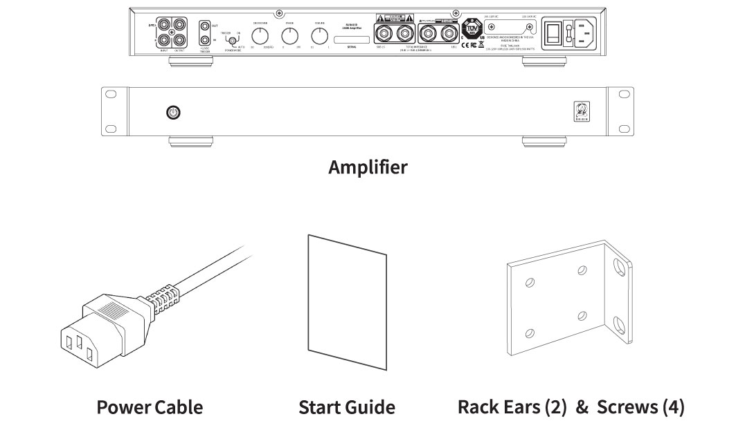
What’s Included
IMPORTANT SAFETY INSTRUCTIONS
1. Read these instructions.
2. Keep these instructions.
3. Heed all warnings.
4. Follow all instructions.
5. Do not use this apparatus near water.
6. Clean only with dry cloth.
7. Do not block any ventilation openings. Install in accordance with the manufacturer’s instructions.
8. Do not install near any heat sources such as radiators, heat registers, stoves, or other apparatus (including amplifiers) that produce heat.
9. Do not defeat the safety purpose of the polarized or grounding type plug. A polarized plug has two blades with one wider than the other. A grounding type plug has two blades and a third grounding prong. The wide bladed or the third prong are provided for your safety. If the provided plug does not fit into your outlet, consult an electrician for replacement of the obsolete outlet.
10. Protect the power cord from being walked on or pinched particularly at plugs, convenience receptacles, and the point where they exit from the apparatus.
11. Only use attachments/accessories specified by the manufacturer.
12. Use only with the cart, stand, tripod, bracket, or table specified by the manufacturer, or sold with the apparatus. When a cart is used, use caution when moving the cart/apparatus combination to avoid injury from tip-over.
13. Unplug this apparatus during lightning storms or when unused for long periods of time.
14. Refer all servicing to qualified service personnel. Servicing is required when the apparatus has been damaged in any way, such as power-supply cord or plug is damaged, liquid has been spilled or objects have fallen into the apparatus, the apparatus has been exposed to rain or moisture, does not operate normally, or has been dropped.
15. The equipment shall be used at maximum 35o C/ 95o F ambient temperature. To help maintain ambient temperature, DO NOT mount in locations with direct sunlight.
16. To reduce the risk of electrical shock, do not open the equipment. For safety reasons it is only allow to the opened by qualified service personnel.
17. WARNING: To reduce the risk of fire or electric shock, do not expose this apparatus to rain or moisture. Additionally, the apparatus shall not be exposed to dripping or splashing and no objects filled with liquids shall be placed on the apparatus.
18. The mains plug is used as the disconnect device and shall remain readily operable.
19. The product shall be used on open bench.
20. No naked flame sources, such as lighted candles, should be placed on the apparatus.
21. The apparatus should be connected to a mains socket outlet with a protective earthing connection.
22. Ventilation should not be impeded by covering the ventilation openings with items, such as newspapers, table-cloths, curtains, etc.
23. This apparatus is suitable for use in tropical climates.

CAUTION:
TO REDUCE THE RISK OF ELECTRIC SHOCK, DO NOT REMOVE COVER OR BACK. NO USER-SERVICEABLE PARTS INSIDE. REFER SERVICING TO AUTHORIZED SERVICE PERSONNEL.
WARNING:
TO PREVENT FIRE OR SHOCK HAZARD, DO NOT EXPOSE THIS APPLIANCE TO RAIN OR MOISTURE. THE APPLIANCE SHALL NOT BE EXPOSED TO DRIPPING OR SPLASHING. NO OBJECTS FILLED WITH LIQUIDS SHALL BE PLACED ON THE APPLIANCE.
Amplifier Features


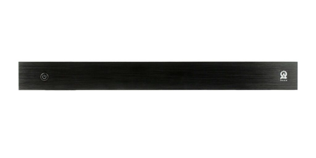
A. Power
Red: Off/Standby
Blue: On/Operating
B. RCA LINE LEVEL INPUTS
LFE IN: Connects the left female RCA input to an LFE output connection on a receiver or pre-amp processor.
L/R IN: Connects the left and right female RCA input to the left and right front output connections on a receiver or pre-amp processor.
C. RCA LINE LEVEL OUTPUTS
OUT: Connects additional amplifiers.
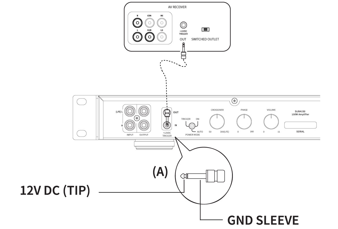
D. 12V TRIGGER IN/OUT
12V TRIGGER IN: Turns on the amp when a 12V signal is received from another 12V trigger device.
12V TRIGGER OUT: Sends a 12V signal to another 12V trigger device.
E. POWER MODES
TRIGGER: Amplifier turns on when 12V signal is detected and off when 12V signal is absent.
AUTO: Auto sense enabled. Amplifier turns on when audio signal is detected. Unit enters standby mode if no signal is sensed after 15 minutes.
ON: Always on. Amplifier does not turn off automatically. Unit turns on/off using the front panel power button.
F. CROSSOVER
Adjusts from 50 to 300 Hz.
NOTE: When using the LFE input, set to LFE so the preamplifier or receiver can control the crossover frequency
G. PHASE
Adjusts blending of the subwoofer with other speakers.
H. VOLUME
Adjusts master volume to the desired listening level.
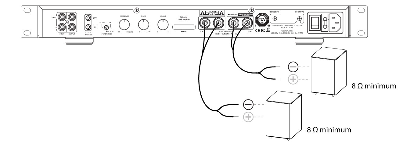
I. SPEAKER OUTPUTS
Connects the speaker wires to the binding posts.
NOTE: Total impedance (SUB 1 + SUB 2) should not be less than 4Ω.
J. VOLTAGE SELECTOR
Selects the appropriate input voltage setting: 120V or 240V.
K. POWER SWITCH
Rocker ON/OFF Switch.
L. FUSE
Additional fuse included for servicing.
M. AC POWER IN
IEC power cord.
Set Up Guide
AMPLIFIER POSITIONING
Placing the amplifier can have a large impact on performance and longevity. Please take the following guidelines into consideration:
• Ensure that the unit is in a well-ventilated area that provides adequate cooling.
• A minimum of 5” should be allowed above and below the amplifier for optimum performance.
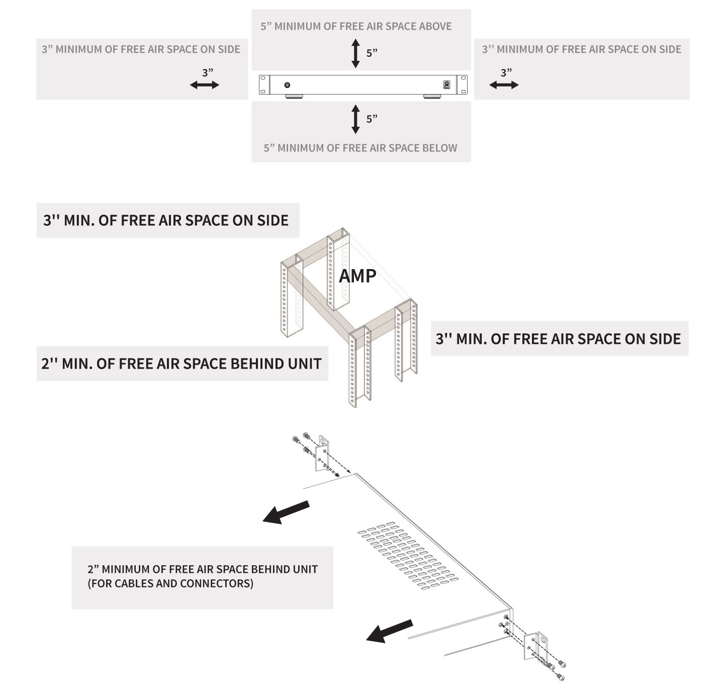
INSTALLATION
• Attach ears to the amplifier if mounting into rack.
• Bottom feet on the amplifier chassis may be removed if necessary.
CONNECTION
! CAUTION: All connections and switching must be done with the amplifier turned off. Connect the power cord last to ensure that the amplifier is off during all the connections and set up.
RCA Line Level
Use high-quality RCA cables that feature low impedance with adequate shielding and high-quality connectors.
Speaker Outputs
Use 14 or 16 gauge stranded two-conductor speaker wire. Connect the appropriate conductor to each screw terminal, observing correct polarity.
! CAUTION: When two subwoofers are connected in parallel, the nominal impedance of each subwoofer should not be less than 8Ω.
SINGLE SUB CONNECTIONS
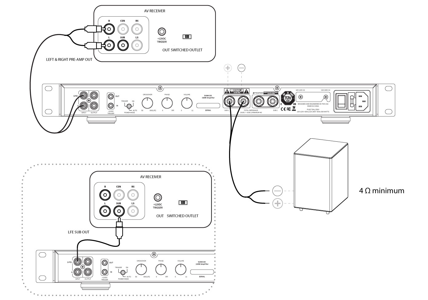
DUAL SUB CONNECTIONS
Connect the appropriate conductor to each screw terminal, observing correct polarity.
12V DC TRIGGER
Connect the 12V trigger output of another device to the 12V trigger input of the amplifier using a high quality 3.5mm (1/8”) mono cable.
Fine Tuning
After making all connections and calibrating the speakers, fine tune the subwoofer as instructed below.
NOTE: When using an AV receiver and the LFE input, set the subwoofer calibration level to the factory setting.
1. Ensure that the subwoofer is plugged in. During initial setup, set the ‘POWER MODES’ switch to the ‘ON’ position. Once calibration is complete, switch to ‘AUTO’ to enable the automatic power-saving mode. For reference, the different modes are as follows:
TRIGGER: Amplifier turns on when 12V signal is detected and off when 12V signal is absent.
AUTO: Auto sense enabled. Amplifier turns on when audio signal is detected. Unit enters standby mode if no signal is sensed after 15 minutes.
ON: Always on. Amplifier does not turn off automatically. Unit turns on/off using the front panel power button.
2. Set the controls to positions that will enable tuning for maximum performance.
VOLUME set to 50%, or 12 o’clock
CROSSOVER set to 175 Hz, or 12 o’clock – OR – set to ‘LFE’ if LFE input is used
PHASE set to 0º
3. Play a movie scene or music track and set the system volume to an average level. Listen to the bass level from the preferred listening position. Adjust the ‘VOLUME’ control as desired.
4. If deeper bass is desired, adjust the ‘CROSSOVER’ control toward the lower frequencies. Experiment with different frequency settings until finding one that sounds best.
NOTE: When using the LFE input, set to LFE and make any crossover adjustments in the preamplifier or receiver crossover settings.
5. Continue listening to music and movie sources using the settings chosen for volume and crossover.
6. Experiment with the phase to find the best setting. Depending on the subwoofer’s placement, the bass may sound louder or deeper when the phase has been optimized. In some cases, adjusting phase will not make a noticeable difference.
NOTE: If deeper bass is desired, adjust the CROSSOVER control toward the lower frequencies. Experiment with different frequency settings until finding one that sounds best. When using the LFE input, set to LFE and make any crossover adjustments in the preamplifier or receiver crossover settings.
7. Play a movie scene or music track and set the system volume to an average level. Listen to the bass level from the preferred listening position. Adjust the VOLUME control as desired.
8. Continue listening to music and movie sources using the settings chosen for volume and crossover.
9. Experiment with the PHASE until finding the best setting. Depending on the subwoofer placement, the bass may sound louder or deeper when the phase has been optimized. In some cases, adjusting phase will make no discernible difference.
Troubleshooting
If you have a problem, try isolating it first. For example, if you’re playing a DVD and there is no sound, try replacing the DVD with an MP3 player to see if you get sound. If it does work, then the problem is with the television, DVD player, or the cables connecting them. If it doesn’t work, the problem will be with the amplifier, speakers, or those cables.
Common Solutions
| PROBLEM | POSSIBLE CAUSES |
|---|---|
| NO SOUND | The volume may be turned down or muted. Check the volume settings volume may be turned down or muted. Check the volume settings on both the amplifier and the DVD player/ television/ computer/ etc. |
| NO SOUND | Make sure the proper source is selected on the amplifier or receiver. |
| NO SOUND | Check the cord connecting the amplifier with the source. The cord may be damaged or plugged into the wrong input or output. |
| NO SOUND | Check the wires connecting the amplifier with the speakers. Make sure they’re connected properly and not damaged in any way. |
| POOR SOUND QUALITY | If you hear something like static, or the sound is cutting in and out, check the audio cables. If the problem increases when a cable is being moved, then the cable is most likely faulty or not connected properly. |
| POOR SOUND QUALITY | Today’s audio systems may have several places to adjust the volume, for example your MP3 player may have a volume control, and your amplifier may also have one. Check to be certain that the volume isn’t turned up past 80% on any device. |
| POOR SOUND QUALITY | Try changing sources to be certain that the selection you’ve chosen is a good quality recording. |
| NO POWER | Ensure the amplifier is plugged into a live outlet. |
| NO POWER | Ensure the power switch on the front panel is on (blue LED). |
| NO POWER | Fuse is blown. Replace with T5AL fuse type. |
| NO POWER | The power mode may be set to the wrong mode for the system’s configuration or setup. |
| UNABLE TO CONTROL MENU | Ensure amplifier is not in Lock Mode. Hold for 10 seconds to unlock menu. |
Technical Assistance
If you have any questions or concerns about installing or using this product, you can reach us through one of the following methods:
Phone: (844) 674-4461
Hours of operation: 8:00am – 5:00pm (Pacific Time), Mon – Fri
Email: sales@originacoustics.com
If you are having technical trouble, please include the model number and briefly explain what steps you took to resolve the problem in your email, or be prepared to answer these questions over the phone. If you are considering returning the product, it’s required that you contact Origin Acoustics prior to any return attempts. This way we can determine if the issue can be resolved without returning the product, or if needed we can provide instructions and support for the return process.
2-Year Limited Warranty
Origin Acoustics warrants to the original retail purchaser only that this Origin Acoustics product will be free from defects in materials and workmanship, provided the speaker was purchased from an Origin Acoustics authorized dealer.
If the product is determined to be defective, it will be repaired or replaced at Origin Acoustics’ discretion. If the product must be replaced yet it is no longer manufactured, it will be replaced with a model of equal to or greater value that is the most similar to the original. If this is the case, installing the replacement model may require mounting modifications; Origin Acoustics will not be responsible for any such related costs.
Requirements & Coverage
This warranty may not be valid if the product was purchased through an unauthorized dealer. This warranty only applies to the individual that made the original purchase, and it cannot be applied to other purchases. The purchaser must be prepared to provide proof of purchase (receipt). This warranty will not be valid if the identifying number or serial number has been removed, defaced, or altered.
Not Covered by Warranty
- Accidental damage
- Damage caused by abuse or misuse
- Damage caused by attempted repairs/modifications by anyone other than Origin Acoustics or an authorized dealer
- Damage caused by improper installation
- Normal wear, maintenance, and environmental issues
- Damage caused by voltage inputs in excess of the rated maximum of the unit
- Damage inflicted during the return shipment
Return Process
Before making any return attempts, it is required that you first contact Origin Acoustics. Return product to Origin Acoustics or your dealer, either in person or by mail. It’s preferable if the product is returned in the original packaging. If this isn’t possible, the customer is responsible for insuring the shipment for the full value of the product.
This warranty is in lieu of all other expressed or implied warranties. Some states do not allow limitations on implied warranties, so this may not apply depending on the customer’s location. (For more information, see Magnuson-Moss Warranty Act.)
| SUBA-150 | |
| Part Number: | AMPSUB1X150 |
| Continuous Power Output: | 80 watts RMS at 8 ohms 150 watts RMS at 4 ohms |
| Input Sensitivity: | 140 mV for full output (L/LFE only driven), 150 W, with level control set to max |
| Frequency Response: | 30-200Hz (EQ MODE set to BYPASS) |
| Distortion: | .10% THD+N 1W/2W 100 Hz |
| Auto On Sensitivity: | 4 mV |
| External Trigger Voltage: | 2.0 V – 20 V |
| 12V Trigger Threshold: | 2.6 V |
| Dimensions: | 16.9” W (19” including rack mounts) 1.75” H (2.1” including feet) 8.1” D (front switch to rear chassis) 8.9” D (front switch rear speaker connector) |
| Weight: | 5.9 lbs |
| Certification: | TUV Listed and tested under UL/EN60065 for US and Canada |