
Professional Collection In-Ceiling Speaker Manual
Install Guide:
Introduction
Thank you for purchasing the Professional Collection speaker. All of Origin Acoustics’ speakers are designed to have excellent sound quality, longevity, and a simple installation process.
This instruction booklet covers the necessary information for a smooth installation, including: the tools you will need, step-by-step instructions for installation, troubleshooting tips for any errors that may occur, and all warranty information. If for any reason you experience problems or if you have installation questions please call us at (844) 674-4461. Hours of operation are 8:00am to 5:00pm (Pacific Time), Monday through Friday.
 (1)")
What’s Included

Certifications
SAFETY AGENCY COMPLIANCE
Origin Acoustics Professional Collection In-Ceiling speakers models PC50, PC60, PC80, PCSUB8 meet the following standards:
- UL 1480A: Standard for Speakers for Commercial and Professional Use
- NFPA 70: National Electric Code
- NFPA 90A: Standard for Installation of Air Conditioning and Ventilation Systems
- UL 2043: Standard for Fire Test for Heat and Visible Smoke Release for Discrete Products and their Accessories Installed in Air-Handling Spaces

Product Features


70V/100V System
70/100-Volt systems are advantageous when the design calls for multiple speakers from the same amplifier and/or long-distance wire runs. The Origin Acoustics 70V/100V loudspeakers feature multiple taps off the transformer adjusted by a rotary switch at the front side of the speaker. The higher the wattage selected the more output will be generated by the speaker. Please note, 70V is common in the U.S. while 100V is the common voltage internationally, especially in Europe. A simple calculation is used to determine how many speakers can be driven on a single amplifier channel. First, for safety purposes, it is recommended to make the calculations based on 80% of the amplifier’s rated power.
- For example, a 500-watt amplifier would safely deliver 400 watts of usable power (500 x 0.8 = 400). Now it is simply a matter of dividing 400 by the tap setting of the speakers.
- For example, if the speakers are set at a 15W tap, the amplifier would be capable of driving 26 speakers per channel. At a 30W tap that would be 13 speakers. At a 60W tap that would be 6 speakers and so on.
As you can see, if you need coverage over a wide area and it requires numerous speakers, a 70V/100V system presents a tremendous advantage. However, it should be noted that the higher the wattage tap, the higher the fidelity and the greater SPL that can be delivered from each speaker. Therefore, it is best to determine the total number of speakers needed and set the taps as high as possible WITHIN the amplifier’s power output rating.
As mentioned, the rotary switch used to adjust the tap setting is located on the front face of the speaker. For this reason, it is best to leave the grilles off until all of the tap settings have been properly adjusted. The table below lists the power tap settings for each model. The same settings are reflected on the rotary switch on the front face of speaker (reference image below).
| MODEL | POSITION | 1 | 2 | 3 | 4 | 5 | 6 |
|---|---|---|---|---|---|---|---|
| PC80 | 70V | 60W | 30W | 15W | 7.5W | OFF | - |
| PC80 | 100V | - | 60W | 30W | 15W | OFF | - |
| PC80 | 6ohm | - | - | - | - | OFF | 6Ω |
| PC60 | 70V | 60W | 30W | 15W | 7.5W | OFF | - |
| PC60 | 100V | - | 60W | 30W | 15W | OFF | - |
| PC60 | 6ohm | - | - | - | - | OFF | 6Ω |
| PC50 | 70V | 30W | 15W | 7.5W | 3.75W | OFF | - |
| PC50 | 100V | - | 30W | 15W | 7.5W | OFF | - |
| PC50 | 6ohm | - | - | - | - | OFF | 6Ω |
| PCSUB8 | 70V | 100W | 50W | 25W | 12.5W | OFF | - |
| PCSUB8 | 100V | - | 100W | 50W | 25W | OFF | - |
| PCSUB8 | 6ohm | - | - | - | - | OFF | 6Ω |
NOTE: The tap setting determines how much wattage each speaker will draw from the amplifier. When daisy-chaining multiple speakers: add the combined wattages of all tap settings, to determine the wattage draw on the amplifier. The combined total wattage should NEVER exceed the wattage rating of the amplifier.
WARNING: The 6 Ω position cannot be used with a 70/100V connection as it will damage or destroy the transformer.
Should you be uncomfortable designing or installing a 70/100V system, or should you have any questions please contact Origin Acoustics Technical Support.
Wire Diagram

Speaker Placement
Speaker placement is determined by several factors like desired SPL, coverage requirements, variance in SPL by location, etc. When the objective is to fill a large area with very little variance (+/- 2dB), then a larger number of speakers are required.
Typically, once the number of speakers has been determined, placing them equidistant from the walls and from each other will deliver the best result. However, due to other factors this may not be possible. Also realize that the higher the ceiling the greater the conical dispersion and therefore the larger coverage area per speaker.
The further the speaker is from the listener, the lower the SPL. As the speaker is placed closer to the wall, bass frequencies will be enhanced. This may or may not be the desired effect but certainly needs to be considered.

| CELING HEIGHT | STANDING LISTENER | SEATED LISTENER |
|---|---|---|
| 8' | 6’ (1.8m) Apart | 10’ (3m) Apart |
| 10' | 10’ (3m) Apart | 14’ (4.3m) Apart |
| 12' | 14’ (4.3m) Apart | 18’ (5.5m) Apart |
| 14' | 18’ (5.5m) Apart | 22’ (6.7m) Apart |
Speaker Wire
The gauge of wire used can have an impact on the performance of your speakers. Generally, speaker wire is determined by the length of the run and wattage utilized. The longer your run is, the smaller the wire gauge must be.
On commercial 70 volt systems, 18 gauge, 2 conductor, stranded and jacketed without shield wire is commonly used.
| WIRE LENGTH | WIRE GAUGE | SYSTEM |
|---|---|---|
| 0 - 200’ (0 – 60m) | 18 | 70V / 100V |
| 200 - 500’ (60 - 150m) | 16 | 70V / 100V |
| Over 500’ (150m) | 14 | 70V / 100V |
In residential systems, for relatively short runs (less than 50 feet) to 6 ohm speakers, 16 gauge wire will be usually suitable.
| WIRE LENGTH | WIRE GAUGE | SYSTEM |
|---|---|---|
| 0 - 50’ (0 - 15m) | 16 | 8 Ohm |
| 50 - 100’ (15 - 45m) | 14 | 8 Ohm |
| Over 100’ (30m) | 12 | 8 Ohm |
Wire Routing
Plan how you will route the wire to the desired speaker location. There are several methods for routing the wire, and you may need to combine several of them.
Behind the Baseboard
The wire can be routed behind the baseboard by cutting a groove out of the back of the baseboard, or by buying a special baseboard designed for concealing wires.
Attic or Basement
When available, you can route the wire through an attic or crawlspace.
Through Walls
When running wires through a wall, be sure to avoid all obstacles such as AC wiring, pipes, and ducts.
Under the Carpet
One option is to lift up the carpet and route “tape wire” under the carpet.
For New Construction
If these speakers are being installed in a new home during construction, the installation process will be a bit different (although much simpler). For these situations, it is recommended you purchase a bracket. Instructions on how to install the speakers are provided with the bracket, or can be found on our website. Visit www.originacoustics.com for more information.
Installation
1. Cut a hole in the drywall using the supplied cutout template (See figure A)
| Figure A. | 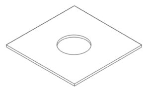 |
2. Connect the wires from your amplifier to the male terminal connector at the rear of the speaker. Strip approximately 3/16” (5mm) of the insulation off each wire. Insert the wire into the correct square opening on the connector. Use a small flathead screwdriver to tighten the corresponding screw to secure the wire. (See Figure B & C).
| Figure B. | 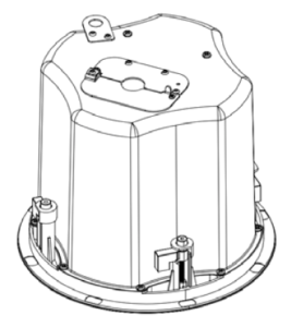 |
| Figure C. | 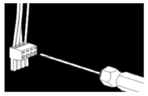 |
3. When using multiple speakers you can connect the speakers either in parallel or in the loop through method as shown below (See Figure D & E).
| Figure D. | 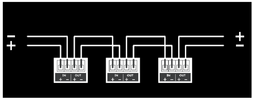 |
| Figure E. | 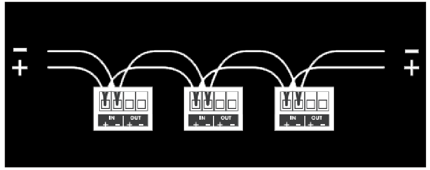 |
4. Make sure all the dogleg (L-shaped) clamps on the speaker are in the upright position and facing to the side, not outwards. Insert the speaker into the hole. Turn the four screws so that the dog legs face outwards and continue turning until they clamp down on the ceiling. When you feel resistance, stop tightening the screws. If you need to remove the speaker, turn the screws in the opposite direction. (See Figure F)
| Figure F. | 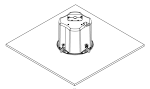 |
5. Determine the proper wattage setting for each speaker in the installation and set each speaker’s transformer tap selector on the front of the speaker accordingly. (See Figure G).
| Figure G. | 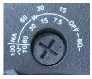 |
6. The speaker has a pivoting tweeter assembly, allowing the treble to be directed to the most suitable location if the speaker is installed off-axis. To pivot the drivers apply light pressure to the ring around the outside edge of the tweeter cone. Take care not to touch or apply pressure to the cone itself. (See Figure H)
| Figure H. | 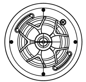 |
7. Fit the grille onto the speaker. (See Figure I)
| Figure I. | 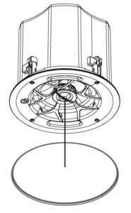 |
Drop Ceiling Installation
The Tile Bridge, consisting of C-bracket and rails, should be used in suspended ceiling installations involving acoustic ceiling tile 2’ x 2’ or 2’ x 4’. The Tile Bridge can also be used in installations when the speakers are mounted into material that will not support their weight.
Insert the two rails and C-bracket through the hole you have cut, mounting them as shown. Using the hardware that is supplied, fasten the C-bracket to the rails as shown (See Figure J & K).
After the C-bracket and tile support rails are installed follow Step 2 through Step 7 in the standard installation instructions.
| Figure J. | 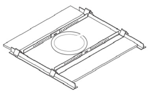 |
| Figure K. | 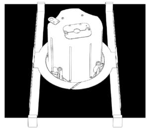 |
Painting the Grille
In some situations, the speakers may look better if the color matched the walls, ceiling, or trim in the room. This can be accomplished by painting the grille. The grille must be painted with spray paint, and most hardware stores will mix a can of paint to match whatever color you need. Before painting, carefully remove the thin cloth on the underside of the grille. Lightly spray the front of the grille with the paint from a distance, being careful not to plug any of the holes.
Diluting the paint with paint thinner will lessen the risk of filling any holes. If a hole gets plugged use a can of compressed air to open it. Once the paint is dry, put the cloth back on the grille.

Safety Agency Compliance
Acoustics Professional Collection In-Ceiling speakers models PC50, PC60, PC80 & PCSUB8 meet the following standards:
UL 1480A: Standard for Speakers for Commercial and Professional Use Scope:
1.1 These requirements cover speakers for indoor and/or outdoor use in dry, damp, wet, or underwater locations and are intended for one or more of the following:
a) Commercial and professional audio systems providing non-emergency sound reinforcement and reproduction in accordance with the National Electrical Code, NFPA 70 (this includes equipment for institutional, industrial use);
b) Non-fire emergency voice-warning systems in accordance with NFPA 70; examples of non-fire emergency-warning systems include, but are not limited to:
- Critical process monitoring (nuclear plant, oil refinery, hazardous chemical processing);
- Distress alert systems (help for handicapped, for life safety, for rape, for robbery);
- Crowd control in public places (sporting arena, theater, shopping mall, transportation center); and
- Non-fire emergency voice-systems covered by the Life Safety Code, NFPA 101.
c) Underwater speakers in accordance with Article 680 of NFPA 70. An underwater speaker is not to be used in a fire alarm system or as an emergency (non-fire) voice-warning system.
1.2 These requirements do not cover the following:
a) Speakers intended for use in hazardous locations as defined in the National Electrical Code, NFPA 70; this includes speakers tested with the requirements in the Standard for Explosion-Proof and Dust-Ignition-Proof Electrical Equipment For Use In Hazardous (Classified) Locations, UL 1203;
b) Speakers intended for personal or private consumer use; this includes speakers for household/domestic use covered by the requirements in the Standard for Audio- Video Products and Accessories, UL 1492 and the Standard for Audio/Video and Musical Instrument Apparatus for Household, Commercial, and Similar General Use, UL 6500;
c) Speakers which are intended for commercial or professional audio applications and which employ integral active electronics; these products are covered in the Standard for Commercial Audio Equipment, UL 813; the Standard for Professional Video and Audio Equipment, UL 1419; and the commercial audio amplifier applications covered in UL 6500; and
d) Speakers intended for security applications; these products are covered in the Standard for Local Burglar Alarm Units and Systems, UL 609; and the Standard for Household Burglar-Alarm System Units, UL 1023.
1.3 Speakers intended for use with fire alarm systems are covered by Standard for Speakers for Fire Alarm and Signaling Systems, Including Accessories, UL 1480. Speakers with integral amplifiers must comply with the requirements in UL 1480 and the Standard for Amplifiers for Fire Protective Signaling Systems, UL 1711.
1.4 Speakers intended for use with emergency and non-emergency systems and having integral amplifiers must comply with this standard in addition to the requirements in the Standard for General-Purpose Signaling Devices and Systems, UL 2017.
1.5 Speakers intended for use in air-handling spaces in accordance with Installation of Air Conditioning and Ventilating Systems, NFPA 90A, shall comply with the requirements in this standard and the requirements in the Standard for Fire Test for Heat and Visible Smoke Release for Discrete Products and Their Accessories
Installed in Air-Handling Spaces, UL 2043.
UL 2043: Standard for Fire Test for Heat and Visible Smoke Release for Discrete Products and their Accessories Installed in Air-Handling Spaces Scope:
1.1 This is a fire test method for determining the fire performance response of discrete products (including, but not limited to electrical, mechanical, and plumbing equipment) intended to be installed in air handling spaces, such as above suspended ceilings or below floors. These products are subjected to an open flame ignition source and evaluated using a product calorimeter.
1.2 This test may be used to determine fire performance and smoke characteristics of discrete, non-continuous building materials where the Test for Surface Burning Characteristics of Building Materials, UL 723, is not applicable.
1.3 The purpose of this test is to determine the rate of heat release and the rate of smoke release of the burning product samples as they relate to the requirements for fire-resistant and low-smoke-producing characteristics in accordance with the provisions of the following codes:
- National Electric Code, NFPA 70; International Mechanical Code, NFPA 5000; Standard for the Installation of Air Conditioning and Ventilating Systems, NFPA 90A.
1.4 This test method does not provide information on the performance of products in other fire or test conditions. This test does not investigate the toxicity of the products of combustion.
1.5 This test does not cover the constructional, electrical, or other performance requirements of the product.
1.6 The Codes noted in 1.3 reference the use of UL 2043 for electrical equipment with combustible outer enclosures. Specifically, the “National Electrical Code” and the “International Mechanical Code” expressly state that electrical equipment with metal enclosures shall be permitted. Consequently, UL 2043 is not intended to apply to electrical equipment with metal outer enclosures unless otherwise specified by end-product-standard requirements.
NFPA 70: Standard for Electrical Safety in the Workplace® Scope:
This standard addresses electrical safety-related work practices, safety-related maintenance requirements, and other administrative controls for employee workplaces that are necessary for the practical safeguarding of employees relative to the hazards associated with electrical energy during activities such as
the installation, inspection, operation, maintenance, and demolition of electric conductors, electric equipment, signaling and communications conductors and equipment, and raceways. This standard also includes safe work practices for employees performing other work activities that can expose them to electrical hazards as well as safe work practices for the following:
- Installation of conductors and equipment that connect to the supply of electricity
- Installations used by the electric utility, such as office buildings, warehouses, garages, machine shops, and recreational buildings that are not an integral part of a generating plant, substation, or control center.
Informational Note:
This standard addresses safety of workers whose job responsibilities entail interaction with electrical equipment and systems with potential exposure to energized electrical equipment and circuit parts. Concepts in this standard are often adapted to other workers whose exposure to electrical hazards is
unintentional or not recognized as part of their job responsibilities. The highest risk for injury from electrical hazards for other workers involve unintentional contact with overhead power lines and electric shock from machines, tools, and appliances.
NFPA 90A: Standard for Installation of Air Conditioning and Ventilation Systems
Scope:
1.1 This standard shall cover construction, installation, operation, and maintenance of systems for air conditioning and ventilating, including filters, ducts, and related equipment, to protect life and property from fire, smoke, and gases resulting from fire or from conditions having manifestations similar to fire. A.1.1 An
air duct system has the potential to convey smoke, hot gases, and flame from area to area and to supply air to aid combustion in the fire area. For these reasons, fire protection of an air duct system is essential to safety to life and the protection of property. However, an air duct system’s fire integrity also enables it to be used as
part of a building’s fire protection system. Guidance for the design of smoke-control systems is provided in NFPA 92, Standard for Smoke Control Systems. Pertinent information on maintenance is provided in Annex B. Maintenance of fire dampers, ceiling dampers, smoke dampers, and combination fire/smoke dampers requirements can be found in NFPA 80, Standard for Fire Doors and Other Opening Protectives, and NFPA 105, Standard for Smoke Door Assemblies and Other Opening Protectives.
Troubleshooting
If you have a problem, try isolating it first. For example, if you’re playing a DVD and there is no sound, try replacing the DVD with an MP3 player to see if you get sound. If it does work, then the problem is with the television, DVD player, or the cables connecting them. If it doesn’t work, the problem will be with the amplifier, speakers, or those cables.
Common Solutions
| PROBLEM | POSSIBLE CAUSES |
|---|---|
| NO SOUND | The volume may be turned down or muted. Check the volume settings volume may be turned down or muted. Check the volume settings on both the amplifier and the DVD player/ television/ computer/ etc. |
| NO SOUND | Make sure the proper source is selected on the amplifier or receiver. |
| NO SOUND | Check the cord connecting the amplifier with the source. The cord may be damaged or plugged into the wrong input or output. |
| NO SOUND | Check the wires connecting the amplifier with the speakers. Make sure they’re connected properly and not damaged in any way. |
| POOR SOUND QUALITY | If you hear something like static, or the sound is cutting in and out, check the audio cables. If the problem increases when a cable is being moved, then the cable is most likely faulty or not connected properly. |
| POOR SOUND QUALITY | Today’s audio systems may have several places to adjust the volume, for example your MP3 player may have a volume control, and your amplifier may also have one. Check to be certain that the volume isn’t turned up past 80% on any device. |
| POOR SOUND QUALITY | Try changing sources to be certain that the selection you’ve chosen is a good quality recording. |
Technical Assistance
If you have any questions or concerns about installing or using this product, you can reach us through one of the following methods:
Phone: (844) 674-4461
Hours of operation: 8:00am – 5:00pm (Pacific Time), Mon – Fri
Email: sales@originacoustics.com
If you are having technical trouble, please include the model number and briefly explain what steps you took to resolve the problem in your email, or be prepared to answer these questions over the phone. If you are considering returning the product, it’s required that you contact Origin Acoustics prior to any return attempts. This way we can determine if the issue can be resolved without returning the product, or if needed we can provide instructions and support for the return process.
Limited 5-Year Warranty
Origin Acoustics warrants to the original retail purchaser only that this Origin Acoustics product will be free from defects in materials and workmanship, provided the speaker was purchased from an Origin Acoustics authorized dealer.
If the product is determined to be defective, it will be repaired or replaced at Origin Acoustics’ discretion. If the product must be replaced yet it is no longer manufactured, it will be replaced with a model of equal to or greater value that is the most similar to the original. If this is the case, installing the replacement model may require mounting modifications; Origin Acoustics will not be responsible for any such related costs.
Requirements & Coverage
This warranty may not be valid if the product was purchased through an unauthorized dealer. This warranty only applies to the individual that made the original purchase, and it cannot be applied to other purchases. The purchaser must be prepared to provide proof of purchase (receipt). This warranty will not be valid if the identifying number or serial number has been removed, defaced, or altered.
Not Covered by Warranty
- Accidental damage
- Damage caused by abuse or misuse
- Damage caused by attempted repairs/modifications by anyone other than Origin Acoustics or an authorized dealer
- Damage caused by improper installation
- Normal wear, maintenance, and environmental issues
- Damage caused by voltage inputs in excess of the rated maximum of the unit
- Damage inflicted during the return shipment
Return Process
Before making any return attempts, it is required that you first contact Origin Acoustics. Return product to Origin Acoustics or your dealer, either in person or by mail. It’s preferable if the product is returned in the original packaging. If this isn’t possible, the customer is responsible for insuring the shipment for the full value of the product.
This warranty is in lieu of all other expressed or implied warranties. Some states do not allow limitations on implied warranties, so this may not apply depending on the customer’s location. (For more information, see Magnuson-Moss Warranty Act.)

| PC80 | |
| Woofer: | 8” IMPP |
| Tweeter: | 1” Silk DSPD™ MMP™ |
| Power Handling (program power): | 120W |
| Power Handling (Continuous Pink Noise) | 60W |
| Freq. Response (-10db): | 41Hz-20kHz |
| Freq. Response (-3db): | 60Hz-20kHz |
| Nominal Coverage Angle: | 100 Degree Conical |
| Sensitivity @1m: | 92db |
| Rated Maximum SPL: | 112db |
| Rated Impedance: | 6Ω Nominal |
| Transformer Taps: | 70V – 60W, 30W, 15W, 7.5W 100V – 60W, 30W, 15W |
| Diameter: | 11 ¼” (286mm) |
| Cutout Diameter: | 10 ½” (266mm) |
| Grille Diameter: | 11 ⅝” (296mm) |
| Mounting Depth: | 9 ½” (242mm) |

| PC60 | |
| Woofer: | 6 ½” IMPP |
| Tweeter: | 1” Silk DSPD™ MMP™ |
| Power Handling (program power): | 80W |
| Power Handling (Continuous Pink Noise) | 40W |
| Freq. Response (-10db): | 50Hz-20kHz |
| Freq. Response (-3db): | 64Hz-20kHz |
| Nominal Coverage Angle: | 115 Degree Conical |
| Sensitivity @1m: | 91db |
| Rated Maximum SPL: | 108db |
| Rated Impedance: | 6Ω Nominal |
| Transformer Taps: | 70V – 60W, 30W, 15W, 7.5W 100V – 60W, 30W, 15W |
| Diameter: | 9 ⅝” (244mm) |
| Cutout Diameter: | 8 ¹³⁄₁₆” (224mm) |
| Grille Diameter: | 10” (254mm) |
| Mounting Depth: | 8” (202mm) |

| PC60S | |
| Woofer: | 6 ½” IMPP |
| Tweeter: | 1” Silk DSPD™ MMP™ |
| Power Handling (program power): | 80 Watts |
| Power Handling (Continuous Pink Noise) | 40 Watts |
| Freq. Response (-10db): | 54Hz-20kHz |
| Freq. Response (-3db): | 81Hz-20kHz |
| Nominal Coverage Angle: | 90 Degree Conical |
| Sensitivity @1m: | 87db |
| Rated Maximum SPL: | 106db |
| Rated Impedance: | 6Ω Nominal |
| Transformer Taps: | 70V – 60W, 35W, 15W, 7.5W 100V – 60W, 30W, 15W |
| Diameter: | 11 ¼” (286mm) |
| Cutout Diameter: | 10 ½” (266mm) |
| Grille Diameter: | 11 ⅝” (296mm) |
| Mounting Depth: | 4 ²³⁄₆₄” (110mm) |

| PC50 | |
| Woofer: | 5 ¼” IMPP |
| Tweeter: | ¾” Silk DSPD™ MMP™ |
| Power Handling (program power): | 60W |
| Power Handling (Continuous Pink Noise) | 30W |
| Freq. Response (-10db): | 54Hz-20kHz |
| Freq. Response (-3db): | 80Hz-20kHz |
| Nominal Coverage Angle: | 120 Degree Conical |
| Sensitivity @1m: | 89db |
| Rated Maximum SPL: | 106db |
| Rated Impedance: | 6Ω Nominal |
| Transformer Taps: | 70V – 30W, 15W, 7.5W, 3.75W 100V – 30W, 15W, 7.5W |
| Diameter: | 8 ¼” (210mm) |
| Cutout Diameter: | 7 ½” (190mm) |
| Grille Diameter: | 8 ¹¹⁄₁₆” (220mm) |
| Mounting Depth: | 8” (202mm) |

| PCSUB8 | |
| Woofer: | 8” IMPP |
| Power Handling (program power): | 200W |
| Power Handling (Continuous Pink Noise) | 100W |
| Freq. Response (-10db): | 39Hz-250Hz |
| Freq. Response (-3db): | 55Hz-250Hz |
| Nominal Coverage Angle: | 180 Degree Conical |
| Sensitivity @1m: | 91db |
| Rated Maximum SPL: | 110db |
| Rated Impedance: | 6Ω Nominal |
| Transformer Taps: | 70V – 100W, 50W, 25W, 12.5W 100V – 100W, 50W, 25W |
| Diameter: | 11 ¼” (286mm) |
| Cutout Diameter: | 10 ½” (266mm) |
| Grille Diameter: | 11 ⅝” (296mm) |
| Mounting Depth: | 9 ½” (242mm) |