
Professional Collection Pendant Speaker Manual
Install Guide:
Introduction
Thank you for purchasing the Professional Collection speaker. All of Origin Acoustics’ speakers are designed to have excellent sound quality, longevity, and a simple installation process.
This instruction booklet covers the necessary information for a smooth installation, including: the tools you will need, step-by-step instructions for installation, troubleshooting tips for any errors that may occur, and all warranty information. If for any reason you experience problems or if you have installation questions please call us at (844) 674-4461. Hours of operation are 8:00am to 5:00pm (Pacific Time), Monday through Friday.

What's Included
Speaker
Grille Removal Key
Gripple® Suspension Kit Containing:
Gripple Rope Grip (2)
Gripple Release Key
Hanging Cable (stainless steel)
Safety Cable (stainless steel)
Cable Ties (3)
Installation Manual
Certifications
SAFETY AGENCY COMPLIANCE
Origin Acoustics Professional Collection Pendant speakers models PP50W, PP50B, PP60W, PP60B, PP80W, PP80B, PSUB8W and PSUB8B, all meet the following standards::
- UL 1480A: Speakers for Fire Protective Signaling Systems.
- CSA-C22.2 No.205: Signaling Equipment for General Signaling and Fire Alarm Signaling, Canada
All speakers shall be installed in accordance with:
- NFPA 70: National Electrical Code
- CSA C22.1: Canadian Electrical Code
Gripple® Suspension Kit included meets the following standard:
- UL 2239: Standard for Safety Hardware for the Support of Conduit, Tubing, and Cable

Product Features

*All product information is subject to change. Please refer to the dealer portal for the latest information.
70V/100V System
70/100-Volt systems are advantageous when the design calls for multiple speakers from the same amplifier and/or long-distance wire runs.
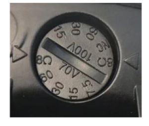
These Professional Collection 70V/100V Pendant Speakers feature multiple taps off the transformer, adjusted by a rotary switch on the front face of the speaker. The higher the wattage selected, the more output will be generated by the speaker.
Please note, 70V is common in the U.S. while 100V is the common voltage internationally, especially in Europe. A simple calculation is used to determine how many speakers can be driven on a single amplifier channel. First, for safety purposes, it is recommended to make the calculations based on 80% of the amplifier’s rated power.
- For example, a 500-watt amplifier would safely deliver 400 watts of usable power (500 x 0.8 = 400). Now it is simply a matter of dividing 400 by the tap setting of the speakers.
- For example, if the speakers are set at a 15W tap, the amplifier would be capable of driving 26 speakers per channel. At a 30W tap that would be 13 speakers. At a 60W tap that would be 6 speakers and so on.
So, if you need coverage over a wide area and it requires numerous speakers, a 70V/100V system presents a tremendous advantage. However, it should be noted that the higher the wattage tap, the higher the fidelity and the greater SPL that can be delivered from each speaker: It is best to determine the total number of speakers needed and set the taps as high as possible WITHIN the amplifier’s power output rating.
As mentioned, the rotary switch used to adjust the tap setting is located on the front face of the speaker. For this reason, it is best to leave the grilles off until all of the tap settings have been properly adjusted.
The following table lists the power tap settings for each model. The same settings are reflected on the rotary switch on the front face of speaker (reference image below).
NOTE: There is an 8Ω setting for both voltages that bypasses the transformer entirely. Use caution to avoid this setting when connected to a 70V/100V amplifier as this can destroy the loudspeaker.
The tap setting determines how much wattage each speaker will draw from the amplifier. When daisy-chaining multiple speakers: add the combined wattages of all tap settings, to determine the wattage draw on the amplifier. The combined total wattage should NEVER exceed the wattage rating of the amplifier.
| MODEL | POSITION | 1 | 2 | 3 | 4 | 5 |
|---|---|---|---|---|---|---|
| PP80 | 70V | - | 60W | 30W | 15W | 7.5W |
| PP80 | 100V | - | - | 60W | 30W | 15W |
| PP80 | 8ohm | 8Ω | - | - | - | - |
| PP60 | 70V | - | 60W | 30W | 15W | 7.5W |
| PP60 | 100V | - | - | 60W | 30W | 15W |
| PP60 | 8ohm | 8Ω | - | - | - | - |
| PP50 | 70V | - | 30W | 15W | 7.5W | 3.75W |
| PP50 | 100V | - | - | 30W | 15W | 7.5W |
| PP50 | 8ohm | 8Ω | - | - | - | - |
| PPSUB8 | 70V | - | 120W | 60W | 30W | 15W |
| PPSUB8 | 100V | - | - | 120W | 60W | 30W |
| PPSUB8 | 8ohm | 8Ω | - | - | - | - |
WARNING:
The 8 Ω position cannot be used with a 70/100V connection as it will damage or destroy the transformer.
Should you be uncomfortable designing or installing a 70/100V system, or should you have any questions please contact Origin Acoustics Technical Support.
Tap Switch for PP60 & PP80
Wire Diagram

Speaker Placement
Speaker placement is determined by several factors like desired SPL, coverage requirements, variance in SPL by location, etc. When the objective is to fill a large area with very little variance (+/- 2dB), then a larger number of speakers are required. Typically, once the number of speakers has been determined, placing them equidistant from the walls and from each other will deliver the best result. However, due to other factors this may not be possible. Also realize that the higher the ceiling the greater the conical dispersion and therefore the larger coverage area per speaker. The further the speaker is from the listener, the lower the SPL. As the speaker is placed closer to the wall, bass frequencies will be enhanced. This may or may not be the desired effect but certainly needs to be considered.

| CELING HEIGHT | STANDING LISTENER | SEATED LISTENER |
|---|---|---|
| 8' | 6’ (1.8m) Apart | 10’ (3m) Apart |
| 10' | 10’ (3m) Apart | 14’ (4.3m) Apart |
| 12' | 14’ (4.3m) Apart | 18’ (5.5m) Apart |
| 14' | 18’ (5.5m) Apart | 22’ (6.7m) Apart |
Speaker Wire
The gauge of wire used can have an impact on the performance of your speakers. Generally, speaker wire is determined by the length of the run and wattage utilized. The longer your run is, the smaller the wire gauge must be.
On commercial 70 volt systems, 18 gauge, 2 conductor, stranded and jacketed without shield wire is commonly used.
| WIRE LENGTH | WIRE GAUGE | SYSTEM |
|---|---|---|
| 0 - 200’ (0 – 60m) | 18 | 70V / 100V |
| 200 - 500’ (60 - 150m) | 16 | 70V / 100V |
| Over 500’ (150m) | 14 | 70V / 100V |
In residential systems, for relatively short runs (less than 50 feet) to 6 ohm speakers, 16 gauge wire will be usually suitable.
| WIRE LENGTH | WIRE GAUGE | SYSTEM |
|---|---|---|
| 0 - 50’ (0 - 15m) | 16 | 8 Ohm |
| 50 - 100’ (15 - 45m) | 14 | 8 Ohm |
| Over 100’ (30m) | 12 | 8 Ohm |
Wire Routing
Plan how you will route the wire to the desired speaker location. There are several methods for routing the wire, and you may need to combine several of them.
Behind the Baseboard
The wire can be routed behind the baseboard by cutting a groove out of the back of the baseboard, or by buying a special baseboard designed for concealing wires.
Attic or Basement
When available, you can route the wire through an attic or crawlspace.
Through Walls
When running wires through a wall, be sure to avoid all obstacles such as AC wiring, pipes, and ducts.
Under the Carpet
One option is to lift up the carpet and route “tape wire” under the carpet.
For New Construction
If these speakers are being installed in a new home during construction, the installation process will be a bit different (although much simpler). For these situations, it is recommended you purchase a bracket. Instructions on how to install the speakers are provided with the bracket, or can be found on our website. Visit www.originacoustics.com for more information.
Installation
CAUTION: INSTALLATION MUST BE DONE BY QUALIFIED PERSONNEL. Failure to comply with these usage recommendations may result in product malfunction and possible damage to property or bodily injury.
1. Insert hanging cable into the Gripple Rope Grip. Pass cable over ceiling anchor point (as shown) or through another secure anchor point of the building structure. The installer is responsible for secured anchoring. (See Figure A)
| Figure A. | 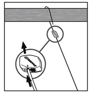 |
2. Pass the returning cable through other hole in the Gripple. (See Figure B).
| Figure B. | 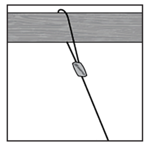 |
3. Latch the suspension hook onto the center hole in the top bracket of the speaker. Adjust to proper height by pulling cable through either end of Gripple. (See Figure C).
| Figure C. | 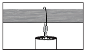 |
D4. Latch secondary safety cable hook onto one of the side holes in the top bracket of the speaker, and loop the cable around a different ceiling support point of the building structure, per Steps 1 & 2. (See Figure D)
| Figure D. | 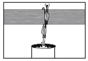 |
5. After height adjustment is final, trim any unneeded extra cable tail wires with trimmer. (See Figure E).
| Figure E. | 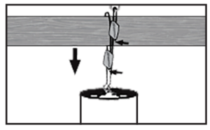 |
How To Use Release Key To Adjust Height Of Speaker
6. Make sure the weight of the load is supported. (See Figure F)
| Figure F. | 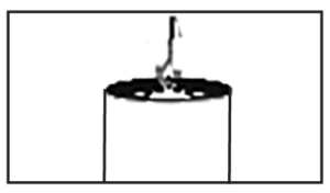 |
7. Insert Release key into small hole at bottom of Gripple. Push in 1/4” to release the cable. (See Figure G)
| Figure G. | 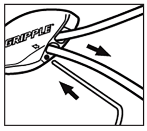 |
8. Adjust height (See Figure H)
| Figure H. | 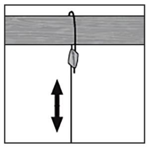 |
9. Remove key and re-secure the load. (See Figure I)
| Figure I. | 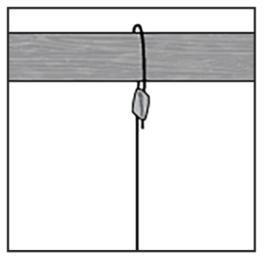 |
10a. Install the 4Pin PVC Connector Cover over the wire cables. (See Figure J)
10b. Connect the wires from your amplifier to the 4Pin Terminal Connector.
Strip approximately 3/16” (5mm) of the insulation off each wire. Insert the wire into the correct square opening on the connector. Use a small flat head screwdriver to tighten the corresponding screw to secure the wire. (See Figures K & L)

11. Plug the male connector into the terminal connector at the rear speaker. Then, slide down the 4Pin PVC Connector Cover over the 4Pin Terminal Connector. (See Figures M & N)

12. When using multiple speakers you can connect the speakers either in parallel or in the loop through method as shown below (See Figure O & P)
Loop Through Connection
| Figure O. |
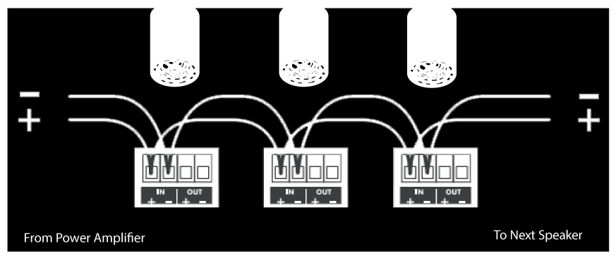 |
Parallel Connection
| Figure P. | 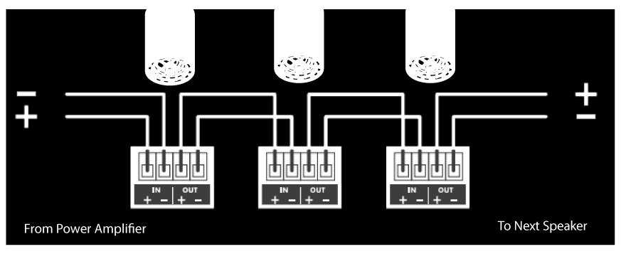 |
13. Determine the proper wattage setting for each speaker in the installation and set each speaker’s transformer tap selector on the front of the speaker accordingly (See Figure Q)
| Figure Q. | 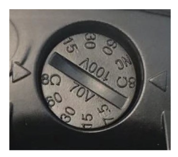 |
14. Fit the grille onto the speaker. (See Figure R)
| Figure R. |  |
Safety Agency Compliance
Origin Acoustics Professional Collection Pendant speakers models PP50W, PP50B, PP60W, PP60B, PP80W, PP80B meet the following standards:
UL 1480A: Standard for Speakers for Commercial and Professional Use Scope:
1.1 These requirements cover speakers for indoor and/or outdoor use in dry, damp, wet, or underwater locations and are intended for one or more of the following:
a) Commercial and professional audio systems providing non-emergency sound reinforcement and reproduction in accordance with the National Electrical Code, NFPA 70 (this includes equipment for institutional, industrial use);
b) Non-fire emergency voice-warning systems in accordance with NFPA 70; examples of non-fire emergency-warning systems include, but are not limited to:
- Critical process monitoring (nuclear plant, oil refinery, hazardous chemical processing);
- Distress alert systems (help for handicapped, for life safety, for rape, for robbery);
- Crowd control in public places (sporting arena, theater, shopping mall, transportation center); and
- Non-fire emergency voice-systems covered by the Life Safety Code, NFPA 101.
c) Underwater speakers in accordance with Article 680 of NFPA 70. An underwater speaker is not to be used in a fire alarm system or as an emergency (non-fire) voice-warning system.
1.2 These requirements do not cover the following:
a) Speakers intended for use in hazardous locations as defined in the National Electrical Code, NFPA 70; this includes speakers tested with the requirements in the Standard for Explosion-Proof and Dust-Ignition-Proof Electrical Equipment For Use In Hazardous (Classified) Locations, UL 1203;
b) Speakers intended for personal or private consumer use; this includes speakers for household/domestic use covered by the requirements in the Standard for Audio- Video Products and Accessories, UL 1492 and the Standard for Audio/Video and Musical Instrument Apparatus for Household, Commercial, and Similar General Use, UL 6500;
c) Speakers which are intended for commercial or professional audio applications and which employ integral active electronics; these products are covered in the Standard for Commercial Audio Equipment, UL 813; the Standard for Professional Video and Audio Equipment, UL 1419; and the commercial audio amplifier applications covered in UL 6500; and
d) Speakers intended for security applications; these products are covered in the Standard for Local Burglar Alarm Units and Systems, UL 609; and the Standard for Household Burglar-Alarm System Units, UL 1023.
1.3 Speakers intended for use with fire alarm systems are covered by Standard for Speakers for Fire Alarm and Signaling Systems, Including Accessories, UL 1480. Speakers with integral amplifiers must comply with the requirements in UL 1480 and the Standard for Amplifiers for Fire Protective Signaling Systems, UL 1711.
1.4 Speakers intended for use with emergency and non-emergency systems and having integral amplifiers must comply with this standard in addition to the requirements in the Standard for General-Purpose Signaling Devices and Systems, UL 2017.
1.5 Speakers intended for use in air-handling spaces in accordance with Installation of Air Conditioning and Ventilating Systems, NFPA 90A, shall comply with the requirements in this standard and the requirements in the Standard for Fire Test for Heat and Visible Smoke Release for Discrete Products and Their Accessories
Installed in Air-Handling Spaces, UL 2043.
12B. CSA-C22.2 No.205: Signaling Equipment for General Signaling and Fire Alarm Signaling, Canada
Scope:
This Standard covers the electrical, fire, and shock hazard requirements for all permanently and cord-connected signal equipment intended for household, commercial and industrial use operating at:
a) nominal system voltage of 120 V for household use;
b) nominal system voltages up to 600 V for commercial and industrial use; and
c) double insulated equipment up to 240 V.
in non-hazardous locations in accordance with the rules of the Canadian Electrical
Code, Part I.
The requirements are not intended to replace other requirements that are mandated by provincial, federal, or authorities having jurisdiction for aspects other than electrical fire and shock hazards, nor do they specify the performance of signal equipment.
Notes:
1) While this document does not address the performance aspects of signaling equipment it does specify requirements for the electrical safety of these devices, including functional safety.
2) Devices that generate radio frequency signals may also be subject to the requirements of Industry Canada.
This Standard covers equipment that performs a sensing and/or signaling function to convey alarm, trouble, status, or event-based information to the user and any subsequent associated activation function. The signal equipment may be stand alone or a part of a larger system. Signaling may employ wired or wireless means.
Note: The equipment can employ audible, visual, motion, or other signaling means such as chimes, gongs, lights, and displays.
This Standard applies to energy management equipment including sensing, monitoring, and actuation devices. The requirements also apply to home automation systems. The signal sensing components meeting the requirement of this Standard can be included in a smart grid application for energy management, other than for industrial applications.
This Standard applies to components that monitor and control activity, and which are:
a) are inter-connected in a wireless sensor network (WSN) in a local network;
b) communicate with local devices that are either wired or wireless.
This Standard also applies to equipment powered by an energy-limited Class 2 power supply.
Lighting photo relay systems, stand-alone or incorporated within a luminaire, and evaluated as a combination in the final application are within the scope of this Standard.
This Standard does not apply to devices that are already covered by requirements of another Part II Standard.
Requirements for a specific type of equipment could have additional requirements as defined in Annexes A, B, D, and E.
Sensors used for medical applications for Class A, B, or C facilities (as defined in CSA Z32) are within the scope of the CAN/CSA-E60691 Series, and are not within the scope of this Standard.
Combustible gas detectors are evaluated to the requirements of CSA C22.2 No. 152 and carbon monoxide alarming devices for residential applications are evaluated to the requirements of CAN/CSA-6.19, and are outside the scope of this Standard.
Low-level water cut-off is evaluated to the requirements of CSA C22.2 No. 24 and is outside the scope of this Standard.
Safety light curtains and similar products are outside the scope of this Standard.
In this Standard, “shall” is used to express a requirement, i.e., a provision that the user is obliged to satisfy in order to comply with the standard; “should” is used to express a recommendation or that which is advised but not required; and “may” is used to express an option or that which is permissible within the limits of the Standard.
Notes accompanying clauses do not include requirements or alternative requirements; the purpose of a note accompanying a clause is to separate from the text explanatory or informative material.
Notes to tables and figures are considered part of the table or figure and may be written as requirements.
Annexes are designated normative (mandatory) or informative (non-mandatory) to define their application.
12C. NFPA 70: Standard for Electrical Safety in the Workplace®
Scope:
This standard addresses electrical safety-related work practices, safety-related maintenance requirements, and other administrative controls for employee workplaces that are necessary for the practical safeguarding of employees relative to the hazards associated with electrical energy during activities such as the installation, inspection, operation, maintenance, and demolition of electric conductors, electric equipment, signaling and communications conductors and equipment, and raceways. This standard also includes safe work practices for employees performing other work activities that can expose them to electrical hazards as well as safe work practices for the following:
- Installation of conductors and equipment that connect to the supply of electricity
- Installations used by the electric utility, such as office buildings, warehouses, garages, machine shops, and recreational buildings that are not an integral part of a generating plant, substation, or control center.
Informational Note:
This standard addresses safety of workers whose job responsibilities entail interaction with electrical equipment and systems with potential exposure to energized electrical equipment and circuit parts. Concepts in this standard are often adapted to other workers whose exposure to electrical hazards is unintentional or not recognized as part of their job responsibilities. The highest risk for injury from electrical hazards for other workers involve unintentional contact with overhead power lines and electric shock from machines, tools, and appliances.
12D. CSA C22.1: Canadian Electrical Code – Part I Safety Standard for Electrical Installations
This Code applies to all electrical work and electrical equipment operating or intended to operate at all voltages in electrical installations for buildings, structures, and premises, including factory-built relocatable and non-relocatable structures, and self-propelled marine vessels stationary for periods exceeding five months and connected to a shore supply of electricity continuously or from time to time, with the following exceptions:
a) installations or equipment employed by an electric, communication, or community antenna distribution system utility in the exercise of its function as a utility, as recognized by the regulatory authority having jurisdiction, and located outdoors or in buildings or sections of buildings used for that purpose;
b) equipment and facilities that are used in the operation of an electric railway and are supplied exclusively from circuits that supply the motive power;
c) installations or equipment used for railway signalling and railway communication purposes, and located outdoors or in buildings or sections of buildings used exclusively for such installations;
d) aircraft; and
e) electrical systems in ships that are regulated under Transport Canada.
For mines and quarry applications, see also CSA M421.
This Code and any standards referenced in it do not make or imply any assurance or guarantee by the authority adopting this Code with respect to life expectancy, durability, or operating performance of equipment and materials so referenced.
12E. UL 2239: Standard for Safety Hardware for the Support of Conduit, Tubing, and Cable
1.1 These requirements cover hardware for the support of conduit, tubing, and cable, such as HANGERS, STAPLES, STRAPS, and similar devices for installation in accordance with the National Electrical Code, NFPA 70, and the Canadian Electrical Code (CEC), Part I.
1.2 These requirements also cover STANDOFFS for nonmetallic-sheathed cable, PROTECTOR PLATES, and PROTECTOR BUSHINGS.
1.3 These requirements do not cover hardware for use with surface raceway, wireway, or busway systems, sprinkler systems, and other piping systems used for fire protection service, hardware for use with lighting fixtures, or hardware for grounding and bonding applications.
1.4 These requirements do not cover:
a) Hardware intended to support boxes (see UL 514A or CSA C22.2 No. 18.1),
b) Conduit and cable fittings (see UL 514B or CSA C22.2 No. 18.3),
c) Reducing washers (see UL 514B or CSA C22.2 No. 18.3),
d) Pulling grips for cable or cord (see UL 514B or CSA C22.2 No. 18.3),
e) Cable ties (see UL 62275 or CSA C22.2 No. 62275 or NMX-J-623-ANCE), or
f) Positioning devices (see UL 1565 or CSA C22.2 No. 18.5).antenna distribution system utility in the exercise of its function as a utility, as recognized by the regulatory authority having jurisdiction, and located outdoors or in buildings or sections of buildings used for that purpose;
g) equipment and facilities that are used in the operation of an electric railway and are supplied exclusively from circuits that supply the motive power;
h) installations or equipment used for railway signalling and railway communication purposes, and located outdoors or in buildings or sections of buildings used exclusively for such installations;
i) aircraft; and
j) electrical systems in ships that are regulated under Transport Canada.
For mines and quarry applications, see also CSA M421.
This Code and any standards referenced in it do not make or imply any assurance or guarantee by the authority adopting this Code with respect to life expectancy, durability, or operating performance of equipment and materials so referenced.
Troubleshooting
If you have a problem, try isolating it first. For example, if you’re playing a DVD and there is no sound, try replacing the DVD with an MP3 player to see if you get sound. If it does work, then the problem is with the television, DVD player, or the cables connecting them. If it doesn’t work, the problem will be with the amplifier, speakers, or those cables.
Common Solutions
| PROBLEM | POSSIBLE CAUSES |
|---|---|
| NO SOUND | The volume may be turned down or muted. Check the volume settings volume may be turned down or muted. Check the volume settings on both the amplifier and the DVD player/ television/ computer/ etc. |
| NO SOUND | Make sure the proper source is selected on the amplifier or receiver. |
| NO SOUND | Check the cord connecting the amplifier with the source. The cord may be damaged or plugged into the wrong input or output. |
| NO SOUND | Check the wires connecting the amplifier with the speakers. Make sure they’re connected properly and not damaged in any way. |
| POOR SOUND QUALITY | If you hear something like static, or the sound is cutting in and out, check the audio cables. If the problem increases when a cable is being moved, then the cable is most likely faulty or not connected properly. |
| POOR SOUND QUALITY | Today’s audio systems may have several places to adjust the volume, for example your MP3 player may have a volume control, and your amplifier may also have one. Check to be certain that the volume isn’t turned up past 80% on any device. |
| POOR SOUND QUALITY | Try changing sources to be certain that the selection you’ve chosen is a good quality recording. |
Technical Assistance
If you have any questions or concerns about installing or using this product, you can reach us through one of the following methods:
Phone: (844) 674-4461
Hours of operation: 8:00am – 5:00pm (Pacific Time), Mon – Fri
Email: sales@originacoustics.com
If you are having technical trouble, please include the model number and briefly explain what steps you took to resolve the problem in your email, or be prepared to answer these questions over the phone. If you are considering returning the product, it’s required that you contact Origin Acoustics prior to any return attempts. This way we can determine if the issue can be resolved without returning the product, or if needed we can provide instructions and support for the return process.
Limited 5-Year Warranty
Origin Acoustics warrants to the original retail purchaser only that this Origin Acoustics product will be free from defects in materials and workmanship, provided the speaker was purchased from an Origin Acoustics authorized dealer.
If the product is determined to be defective, it will be repaired or replaced at Origin Acoustics’ discretion. If the product must be replaced yet it is no longer manufactured, it will be replaced with a model of equal to or greater value that is the most similar to the original. If this is the case, installing the replacement model may require mounting modifications; Origin Acoustics will not be responsible for any such related costs.
Requirements & Coverage
This warranty may not be valid if the product was purchased through an unauthorized dealer. This warranty only applies to the individual that made the original purchase, and it cannot be applied to other purchases. The purchaser must be prepared to provide proof of purchase (receipt). This warranty will not be valid if the identifying number or serial number has been removed, defaced, or altered.
Not Covered by Warranty
- Accidental damage
- Damage caused by abuse or misuse
- Damage caused by attempted repairs/modifications by anyone other than Origin Acoustics or an authorized dealer
- Damage caused by improper installation
- Normal wear, maintenance, and environmental issues
- Damage caused by voltage inputs in excess of the rated maximum of the unit
- Damage inflicted during the return shipment
Return Process
Before making any return attempts, it is required that you first contact Origin Acoustics. Return product to Origin Acoustics or your dealer, either in person or by mail. It’s preferable if the product is returned in the original packaging. If this isn’t possible, the customer is responsible for insuring the shipment for the full value of the product.
This warranty is in lieu of all other expressed or implied warranties. Some states do not allow limitations on implied warranties, so this may not apply depending on the customer’s location. (For more information, see Magnuson-Moss Warranty Act.)

| PP80 | |
| Woofer: | 8” (203mm) Polypropylene |
| Tweeter: | 1” (25mm) Silk DSPD™ MMP™ |
| Power Handling (program power): | 200W |
| Power Handling (Continuous Pink Noise) | 100W |
| Freq. Response (-10db): | 42Hz-20kHz |
| Freq. Response (-3db): | 57Hz-20kHz |
| Nominal Coverage Angle: | 110 Degree Conical |
| Sensitivity @1m: | 90db |
| Rated Maximum SPL: | 110db |
| Rated Impedance: | 8Ω Nominal |
| Transformer Taps: | 70V – 60W, 30W, 15W, 7.5W 100V – 60W, 30W, 15W |
| Diameter: | 10” (254mm) |
| Length: | 16 ¼” (412mm) |
| Features: | 8” Passive Radiator |

| PP60 | |
| Woofer: | 6 ½” (165mm) Polypropylene |
| Tweeter: | 1” (25mm) Silk DSPD™ MMP™ |
| Power Handling (program power): | 130W |
| Power Handling (Continuous Pink Noise) | 65W |
| Freq. Response (-10db): | 50Hz-20kHz |
| Freq. Response (-3db): | 62Hz-20kHz |
| Nominal Coverage Angle: | 120 Degree Conical |
| Sensitivity @1m: | 88db |
| Rated Maximum SPL: | 108db |
| Rated Impedance: | 8Ω Nominal |
| Transformer Taps: | 70V – 60W, 30W, 15W, 7.5W 100V – 60W, 30W, 15W |
| Diameter: | 8 ¼” (210mm) |
| Length: | 12 5⁵⁄₁₆” (313mm) |
| Features: | 6 ½” Passive Radiator |

| PP50 | |
| Woofer: | 5 ¼” (133mm) Polypropylene |
| Tweeter: | 1” (25mm) Silk DSPD™ MMP™ |
| Power Handling (program power): | 100W |
| Power Handling (Continuous Pink Noise) | 50W |
| Freq. Response (-10db): | 57Hz-20kHz |
| Freq. Response (-3db): | 75Hz-20kHz |
| Nominal Coverage Angle: | 120 Degree Conical |
| Sensitivity @1m: | 87db |
| Rated Maximum SPL: | 105db |
| Rated Impedance: | 8Ω Nominal |
| Transformer Taps: | 70V – 30W, 15W, 7.5W, 3.75W 100V – 30W, 15W, 7.5W |
| Diameter: | 6 ¹¹⁄₁₆” (170mm) |
| Length: | 10 ½” (267mm) |
| Features: | 5” Passive Radiator |

| PPSUB8 | |
| Woofer: | 8” (203mm) Polypropylene |
| Power Handling (program power): | 200W |
| Power Handling (Continuous Pink Noise) | 125W |
| Freq. Response (-10db): | 40Hz-20kHz |
| Freq. Response (-3db): | 55Hz-20kHz |
| Nominal Coverage Angle: | 180 Degree Conical |
| Sensitivity @1m: | 90db |
| Rated Maximum SPL: | 110db |
| Rated Impedance: | 8Ω Nominal |
| Transformer Taps: | 70V -120W, 60W, 30W, 15W 100V – 120W, 60W, 30W |
| Diameter: | 10” (254mm) |
| Length: | 16 ¼” (412mm) |
| Features: | 8” Passive Radiator |