
Reusable New Construction Bracket (REBR68) Manual
Install Guide:
Specifications:
Introduction
Thank you for purchasing the REBR68 Reusable New Construction Bracket. At Origin Acoustics, we take pride in providing you with a high quality product. All of Origin Acoustics’ speakers are designed to have excellent sound quality, longevity, and a simple installation process.
This instruction booklet covers the necessary information for a smooth installation, including: the tools you will need, step-by-step instructions for installation, troubleshooting tips for any errors that may occur, and all warranty information. If for any reason you experience problems or if you have installation questions please call us at (844) 674-4461. Hours of operation are 8:00am to 5:00pm (Pacific Time), Monday through Friday.

What’s Included

Tools Required
-
Drywall Saw
-
Measuring Tape
-
Drill
-
Screws
-
Hammer
-
Nails
About the Reusable Bracket
Our reusable bracket REBR68 is designed to be used as a new construction bracket for our Director 6” and 8” speakers. Additionally, the center plastic ring can be removed once the sheetrock has been cut to accommodate our speaker. With the plastic ring, you can simply attach a new set of installation wings and reuse the bracket for the next project you’re working on. This will save you time and cost for your larger new home projects.
Installation
1. Installing the Wings
Once desired speaker location is found, locate desired wing positions on the reusable bracket that coordinate with the ceiling joists for a secure fit. Line up and place the four pins of the bracket to the four holes of the wing. Attach the wings by locking in place with the included metal clips. (See Figure A).
| Figure A. | 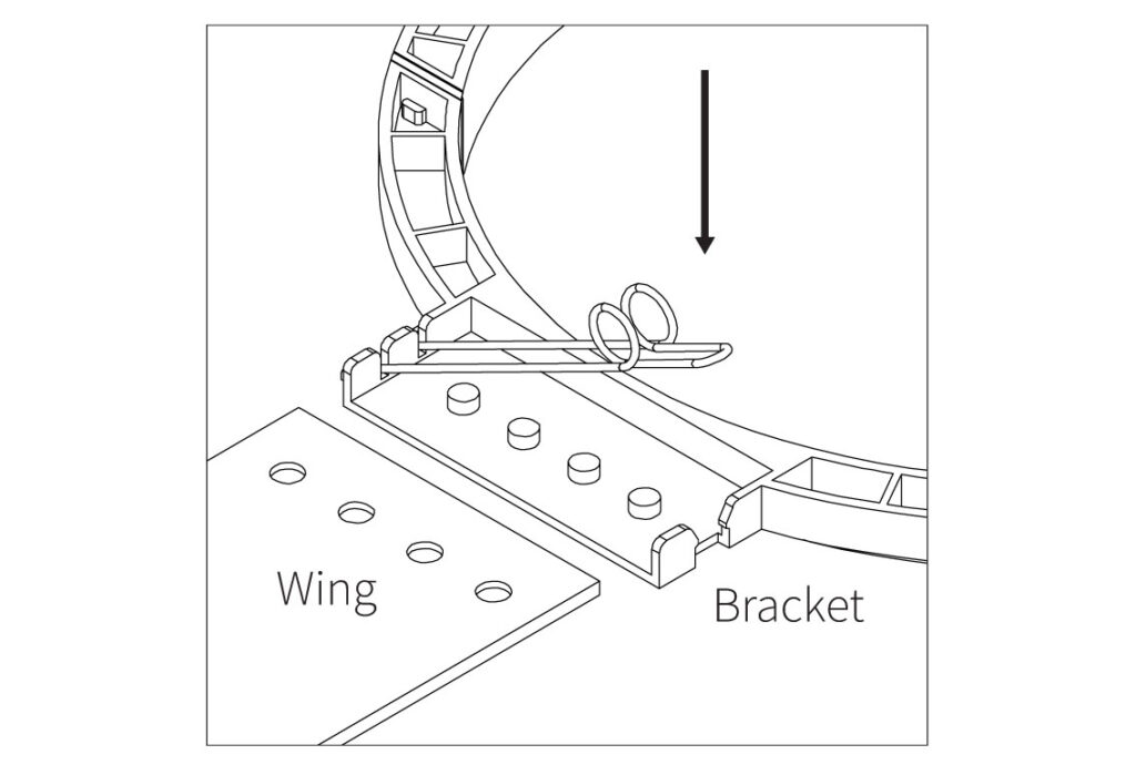 |
2. Placing the Bracket
Place the bracket between ceiling joists using the ruler marks for your desired location. Either nail or staple the bracket wings to the joists. (See Figure B).
| Figure B. | 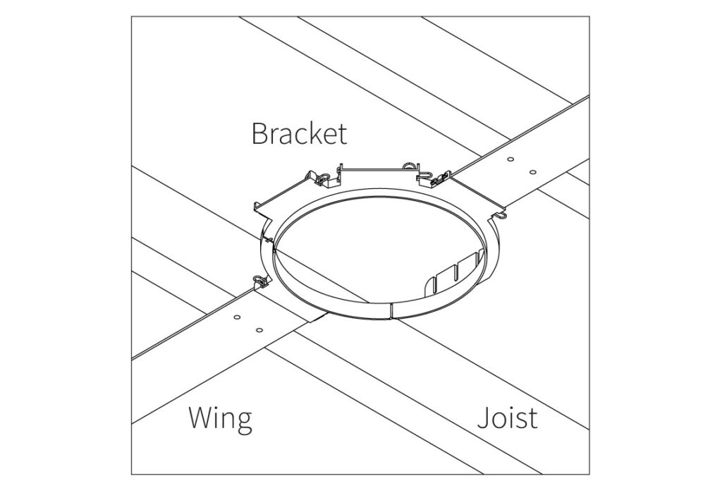 |
3. Cutting the Hole
Make sure the “lip” of the bracket is facing down into the room. The “lip” allows the bracket to act as a template for cutting the speaker cutout in the sheet rock. Cut along the inside of the bracket hole where the hole should be. Use a keyhole or drywall saw to cut the hole. (See Figure C)
| Figure C. | 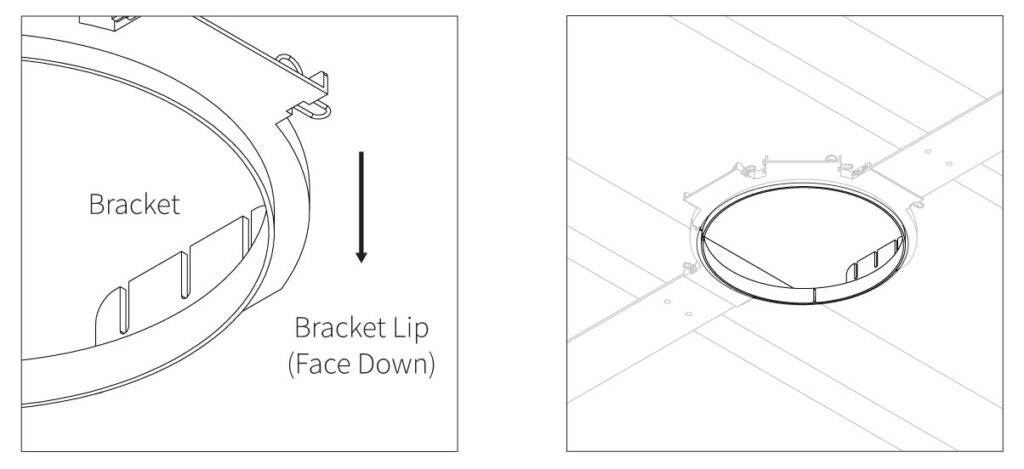 |
4. Uninstalling the Bracket
To remove the bracket, squeeze the metal clips to loosen each wing. The wings can be cut if needed. They will not be used again. Once the wings are detached, unsnap the bracket at the joint to allow the bracket to bend for easy removal through the cutout. The bracket can be used again by adding another pair of REBRW20 wings. (See Figure D).
| Figure D. | 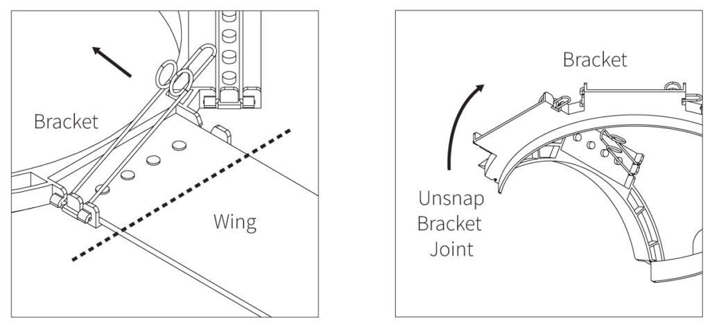 |
Technical Assistance
If you have any questions or concerns about installing or using this product, you can reach us through one of the following methods:
Phone: (844) 674-4461
Hours of operation: 8:00am – 5:00pm (Pacific Time), Mon – Fri
Email: sales@originacoustics.com
If you are having technical trouble, please include the model number and briefly explain what steps you took to resolve the problem in your email, or be prepared to answer these questions over the phone. If you are considering returning the product, it’s required that you contact Origin Acoustics prior to any return attempts. This way we can determine if the issue can be resolved without returning the product, or if needed we can provide instructions and support for the return process.