MOS36K Minimal Opening System Manual
Install Guide:
Introduction
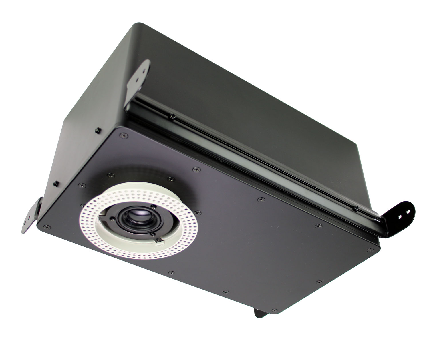
Thank you for choosing the Origin MOS36K Minimum Opening System. Our smallest yet largest feat so far, the Minimal Opening System™ is a revolutionary fully in-ceiling audio system that mimics the appearance of 4’’ designer lighting.
Customized to match the unique appearance of home lighting, the custom finish blends seamlessly into the ceiling alongside lights for a sophisticated uniform look. The included Trim-Ring Kit includes 5 different designs, offering the latest, invisible flush mount trim-ring options, and both round & square grilles, allowing the ideal trim to be selected to match any interior.
This instruction booklet cover the necessary information for a smooth installation, including: the tools you will need, step-by-step instructions for installation, troubleshooting tips for any errors that may occur, and all warranty information. If for any reason you experience problems or if you have installation questions please call us at (844) 674-4461. Hours of operation are 8:00am to 5:00pm (Pacific Time), Monday through Friday.
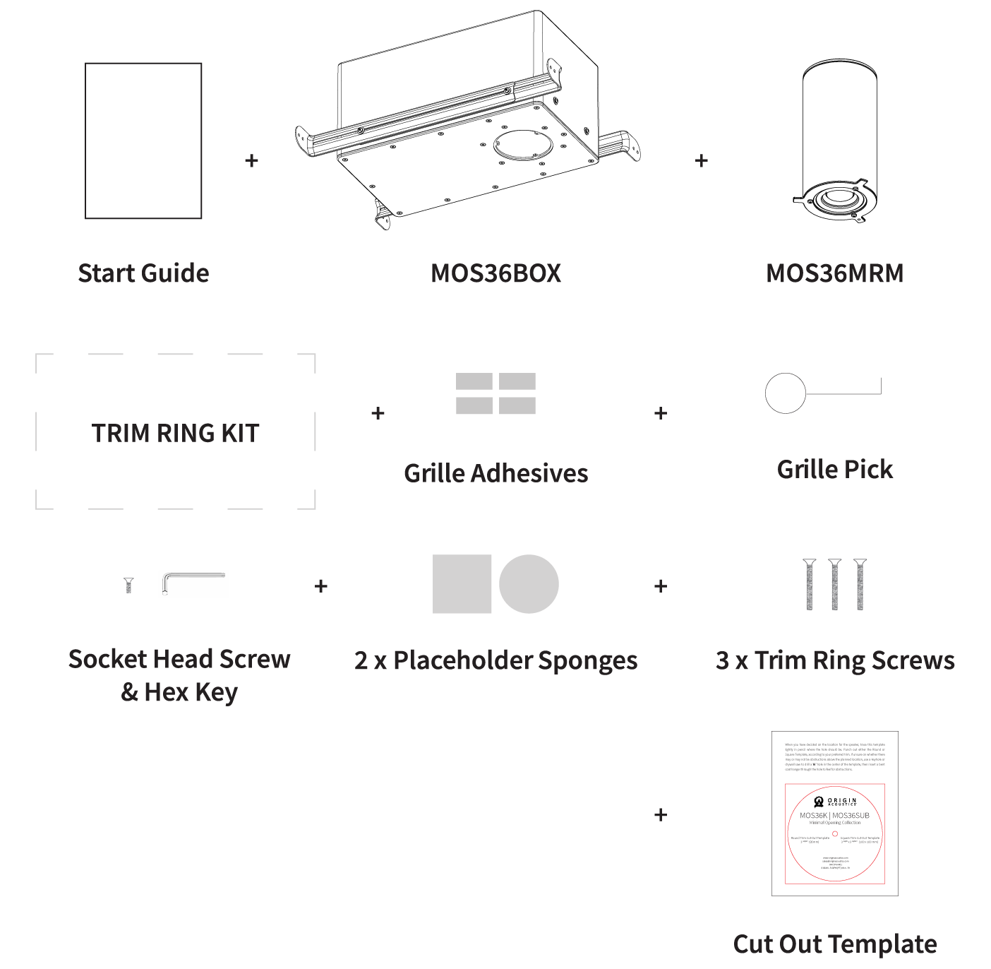
What’s Included
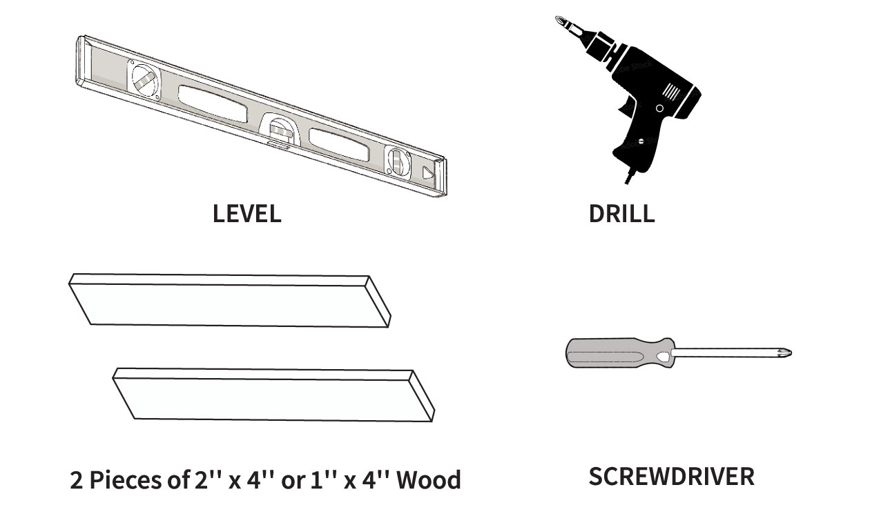
Tools Required
MOS36K Finish Trim Kit Overview
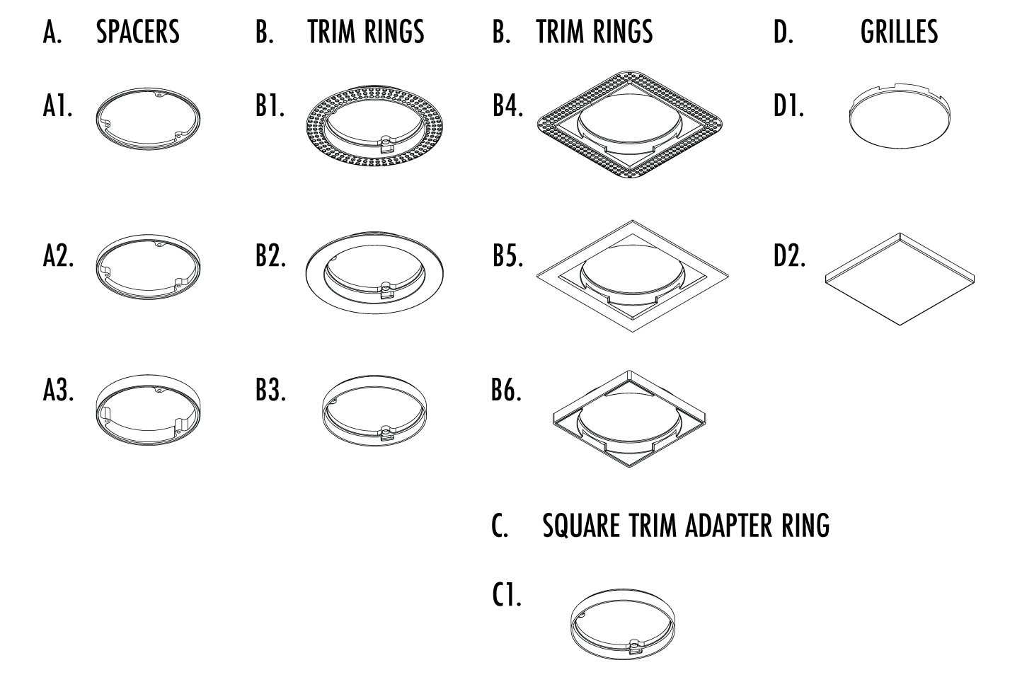
Typical Parts Order
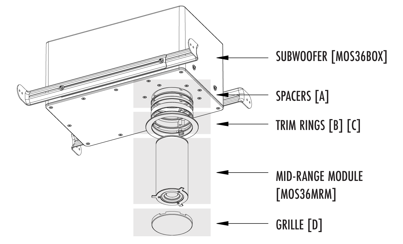
MOS36K Trim Ring Kit
The Trim Ring Kit includes the following pieces:
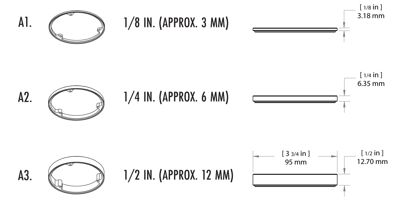
A. Spacer Options
B. Trim Ring Options
C. Square Trim Adapter Ring

D. Grille Options

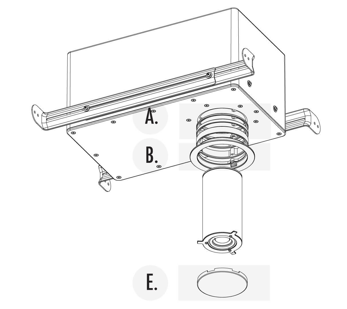
MOS36K Round Trim Setup
A. SPACERS
There are 3 included spacer pieces:
A1. Spacer: 1/8 in. (3.18 mm) Depth
A2. Spacer: 1/4 in. (6.35 mm) Depth
A3. Spacer: 1/2 in. (12.70 mm) Depth
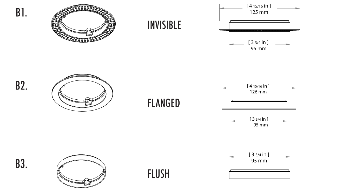
B. ROUND TRIM RINGS
B1. Round Invisible Trim: 4 15/16 in. (125 mm) Diameter
B2. Round Flanged Trim: 4 15/16 in. (126 mm) Diameter
B3. Round Flush Trim: 3 3/4 in. (95 mm) Diameter
D1. ROUND PLACEHOLDER SPONGE
E1. ROUND GRILLE

MOS36K Square Trim Setup
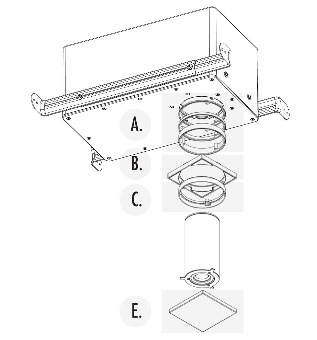
A. SPACERS
There are 3 included spacer pieces:
A1. Spacer: 1/8 in. (3.18 mm) Depth
A2. Spacer: 1/4 in. (6.35 mm) Depth
A3. Spacer: 1/2 in. (12.70 mm) Depth
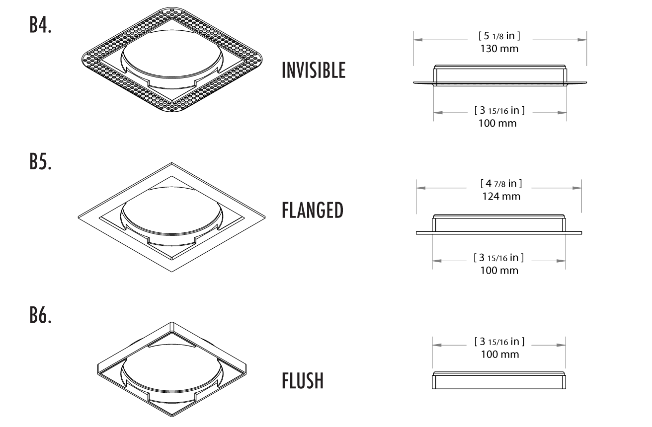
B. SQUARE TRIM RINGS
B4. Square Invisible Trim: 5 1/8 in. (130 mm) Width
B5. Square Flanged Trim: 4 7/8 in. (124 mm) Width
B6. Square Flush Trim: 3 15/16 in. (100 mm) Width
C1. MRM ADAPTER RING FOR SQUARE TRIM ATTACHMENT
Required for Square Trim Ring Installation:
3 3/4 in. (95 mm) Diameter
D1. SQUARE PLACEHOLDER SPONGE
E1. SQUARE GRILLE

MOS36K Mounting Steps
1. Mount temporary holders to ceiling joists.
Cut a couple of 2” x 4”s or 1” x 4”s, a few inches wider than the ceiling joists. Then with a couple of drywall screws, mount the temporary holders to the joists. (Drywall screws not included).
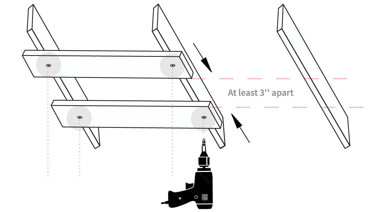
These temporary holders will help you hold up the MOS36K and make the speaker mount flush to the future drywall. Using a level, check that your temporary holders are evenly level, adjusting as needed.
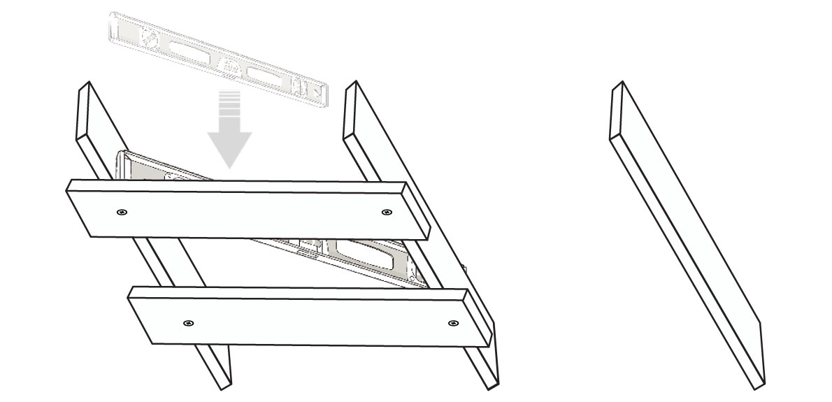
2. Adjust the rails, as neccessary, to fit ceiling joists.
Place MOS36BOX in desired final location.
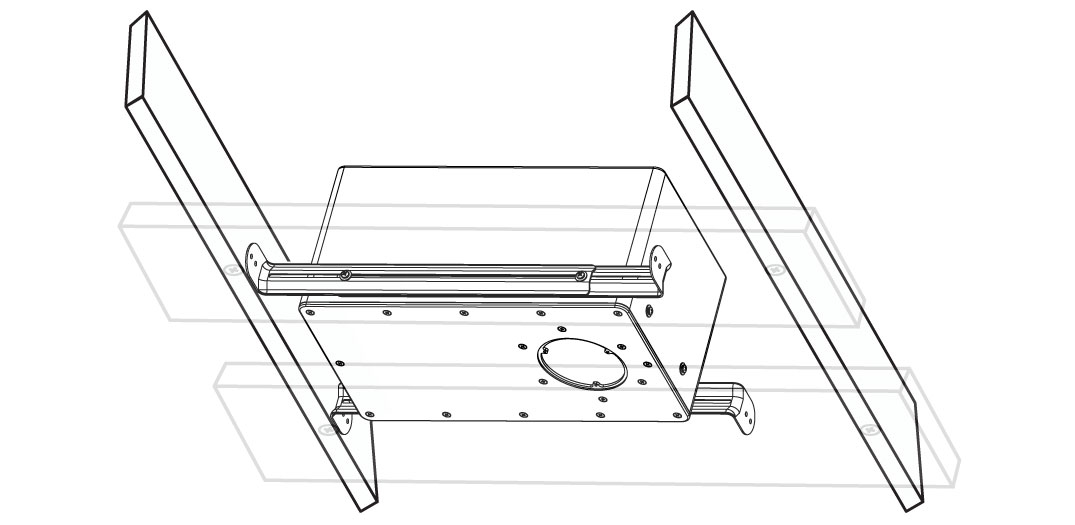
*Ensure the rail ends are turned outwards.*
Then, using a Phillips screwdriver, loosen the screws on each side of the system rails, and extend them so they reach the ceiling joists. Afterwards, make sure to re-tighten screws once the rail length matches the ceiling joists.
NOTE: The cabinet also has screw openings on the short sides so you can move the rails from the long side to the short sides for tight space installations.
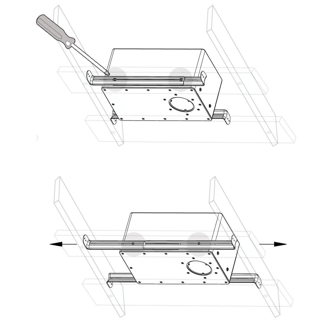
3. Securely fix the rail brackets to the joists.
Use a drill and the included screws. Ensure each the screws on each side of the rails are evenly inserted, for a level positioning.

4. Remove the temporary wood supports from the joists.

5. Ensure the face of the speaker is plumb with the joists.

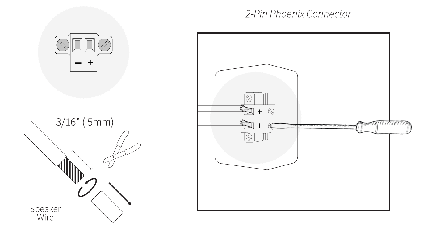
6. Speake wire connection:
To connect the speaker wire to the 2-Pin Phoenix Connector on the Subwoofer module, strip approximately 3/16” (5mm) of the insulation off each wire, and to avoid stray strands, twist them at the end.
Insert each wire into the square opening with the correct polarity, on the phoenix connector. Use a small flathead screwdriver to tighten the corresponding screw to secure the wire. Lastly, using the screwdriver, tighten the 2-Pin Connector Housing to the MOS36K Subwoofer Enclosure.
7. Ceiling Cut Out Steps
Use the cut-out template to mark the cut-out for the speaker (MOS36MRM) on the drywall/ surface material.
Trace along the inside of the Cut-Out Template, then use a keyhole or drywall saw to cut out the hole.

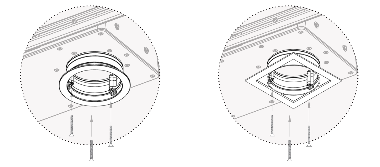
8. Installing Flanged or Flush Trims:
The Flanged and Flush trims can be added to the cutout, without drywalling over. If the Port Tube cover does not reach the edge of the drywall, or if using sheetrock that is thicker than ½’’, attach the appropriate number of spacers, according to the depth of the drywall ceiling, for the trim to fit.
NOTE: If using a square trim, place the MRM Adapter Ring (Piece: C1) inside, with the Screw Holes facing towards the Port-Tube, and screw into the remaining Spacers and Subwoofer Enclosure as normal.
-
Installing Flanged Trim
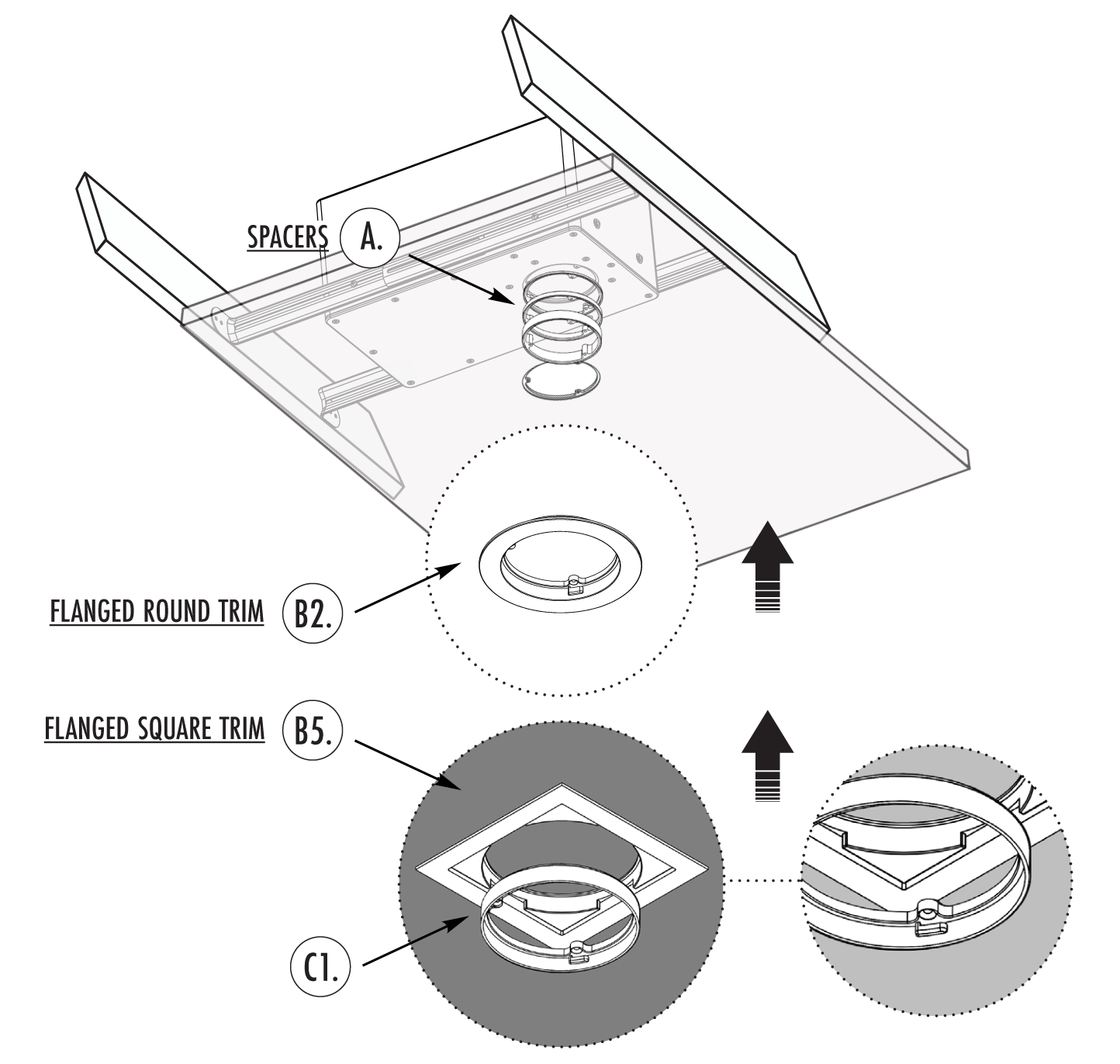
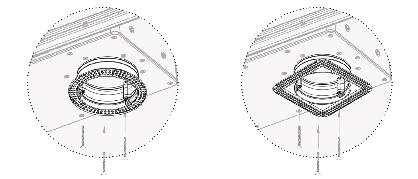
Then, install the desired rim ring over the spacers and secure the trim ring into all spacers & subwoofer enclosure, using the 3 included Trim Ring Screws.
-
Installing Flush Trim
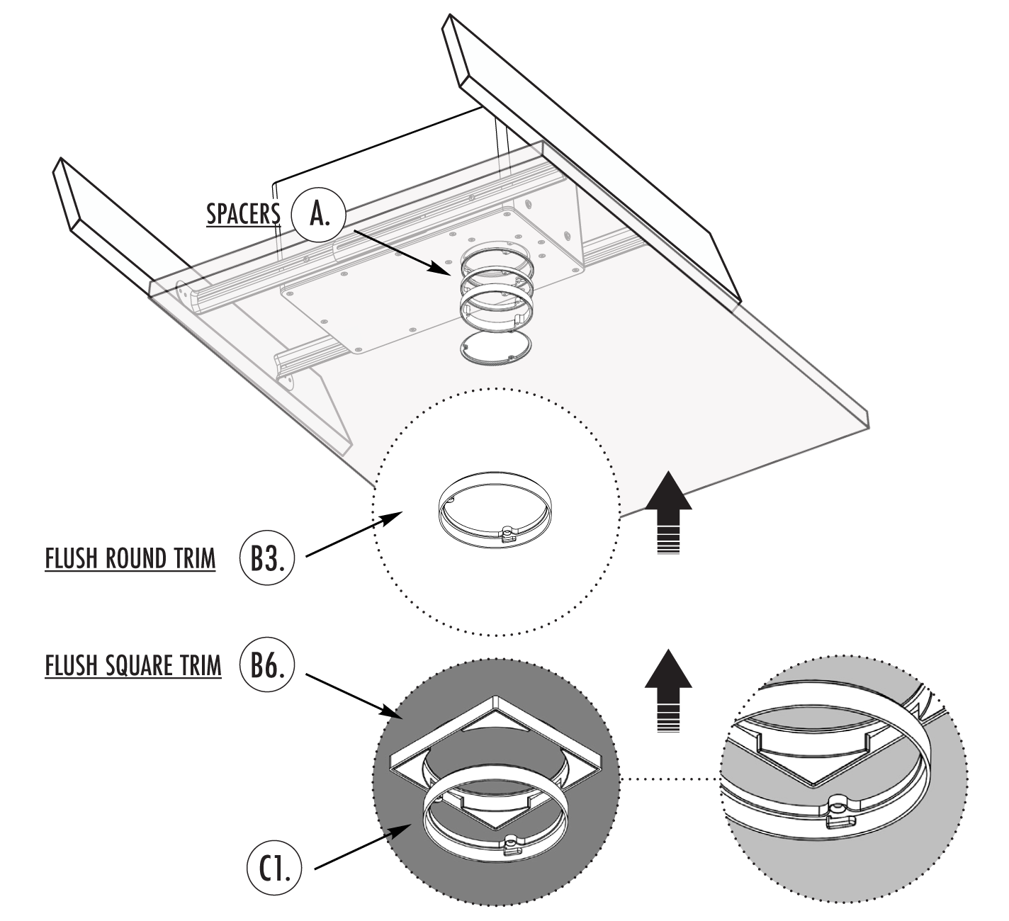
Then, install the desired trim ring over the spacers and secure the trim ring into all spacers & subwoofer enclosure, using the 3 included Trim Ring Screws.
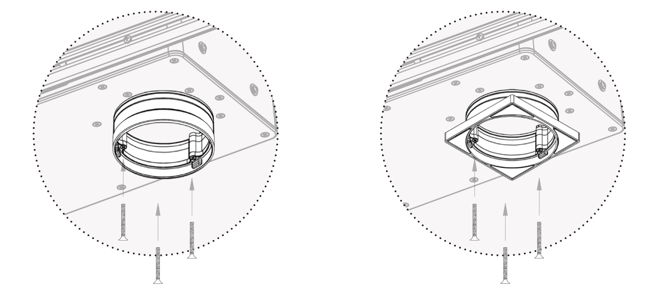
-
Installing Invisible Trims
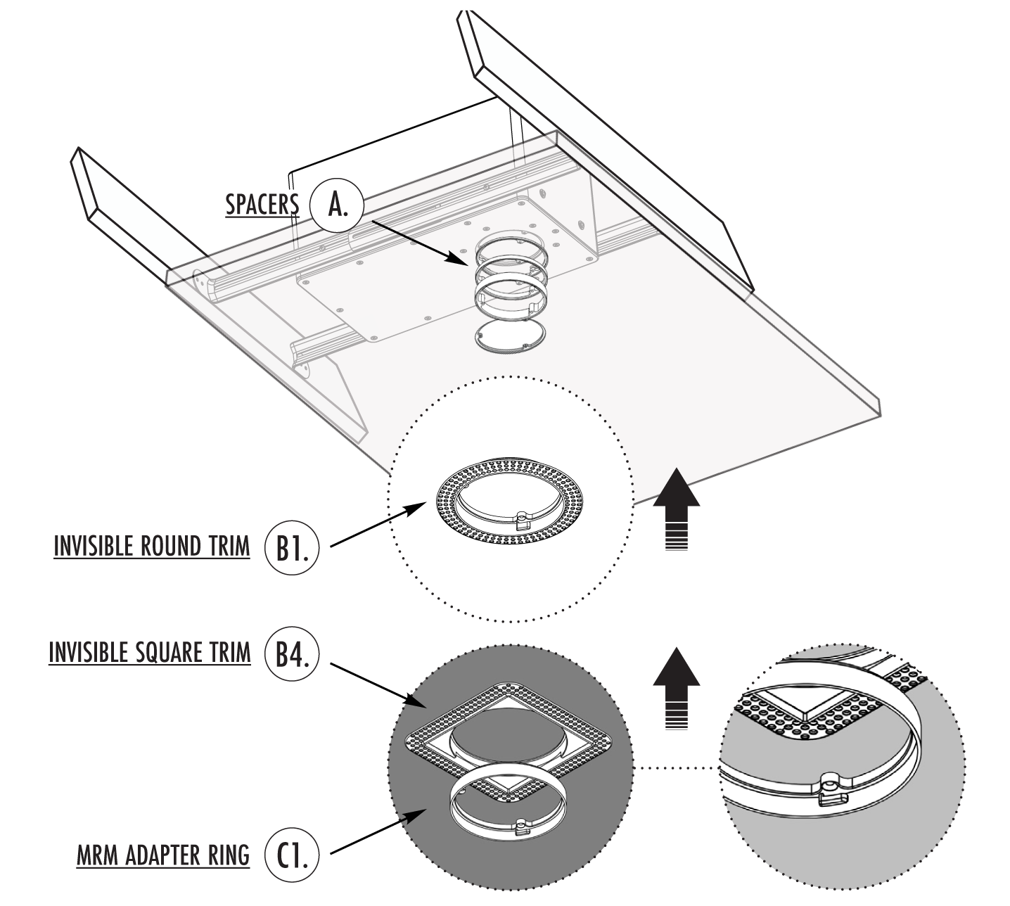
Then, install the desired trim ring over the spacers and secure the trim ring into all spacers & subwoofer enclosure, using the 3 included Trim Ring Screws.
Testing the Speaker
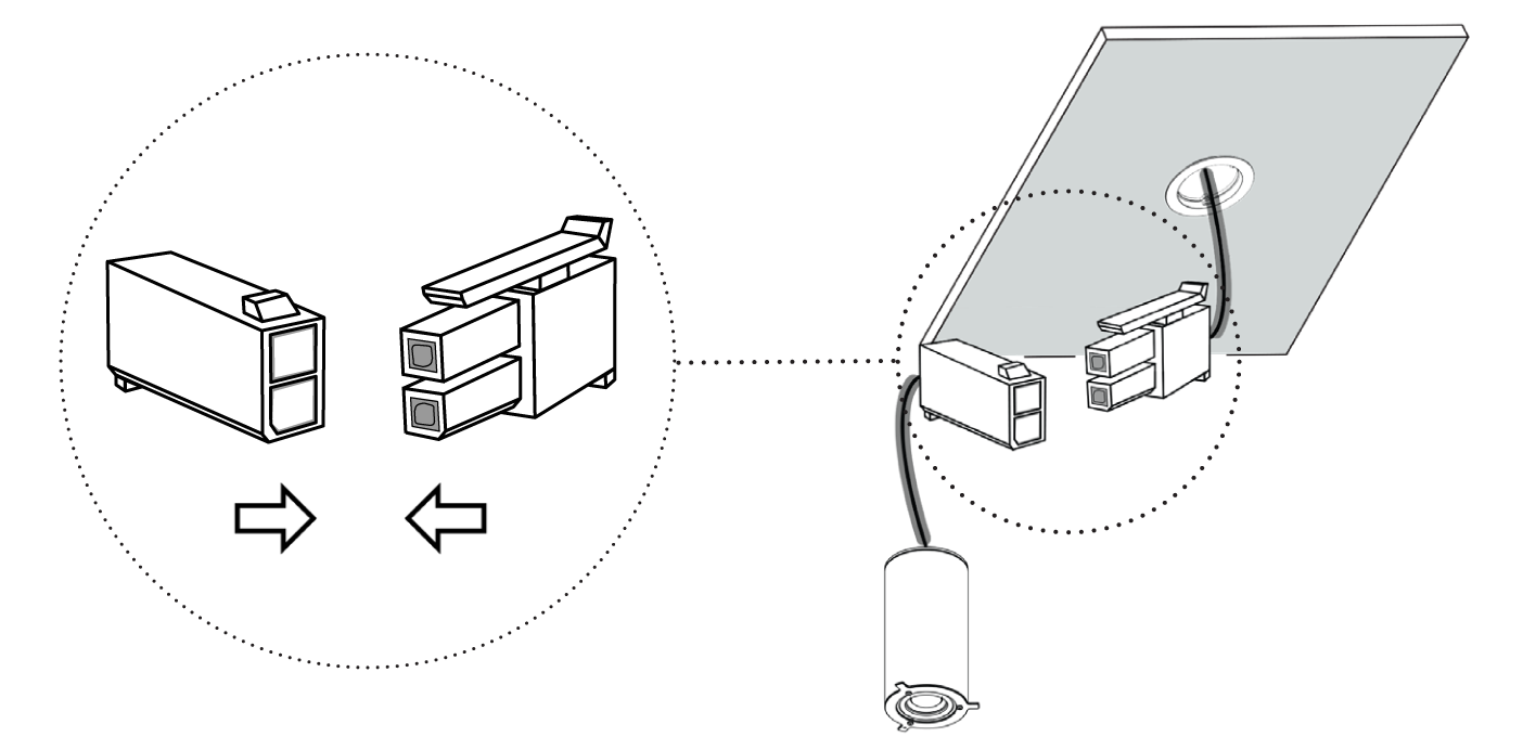
The MOS36MRM (Mid-Range Module) should be inserted into the MOS36BOX Subwoofer assembly to test the unit, before plaster work is performed. Securely fix the 2-Pin Connectors together, from the MOS36BOX to the MOS36MRM piece, for a sound test.
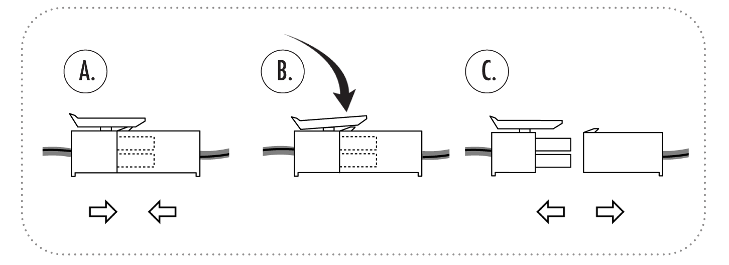
To disconnect/release, press down on plastic latch.
Applying Drywall / Surface Material
Next, before installing the drywall over the Invisible Trim, place the correct Placeholder Sponge inside, to protect the cut-out hole & port tube from any debris during the drywalling process.
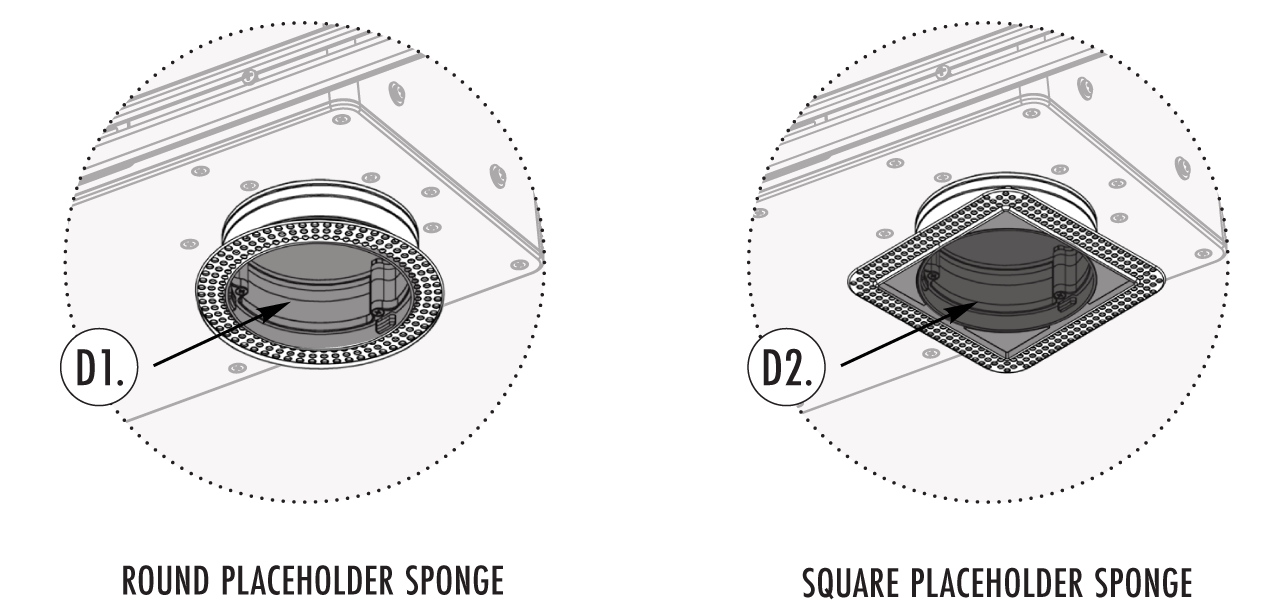
Apply the drywall/ surface material, plaster & paint, over the invisible trim, using mesh tape to cover any installation seams. Apply joint compound and level out compound to conceal seams. Make sure to mud up to the rim of the trim ring spacer. Then remove the Placeholder Sponge.
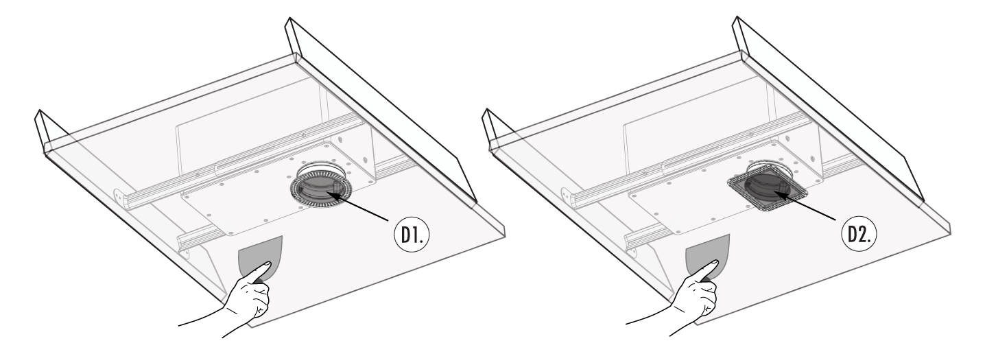
Securing the Mid-range Module (Speaker)
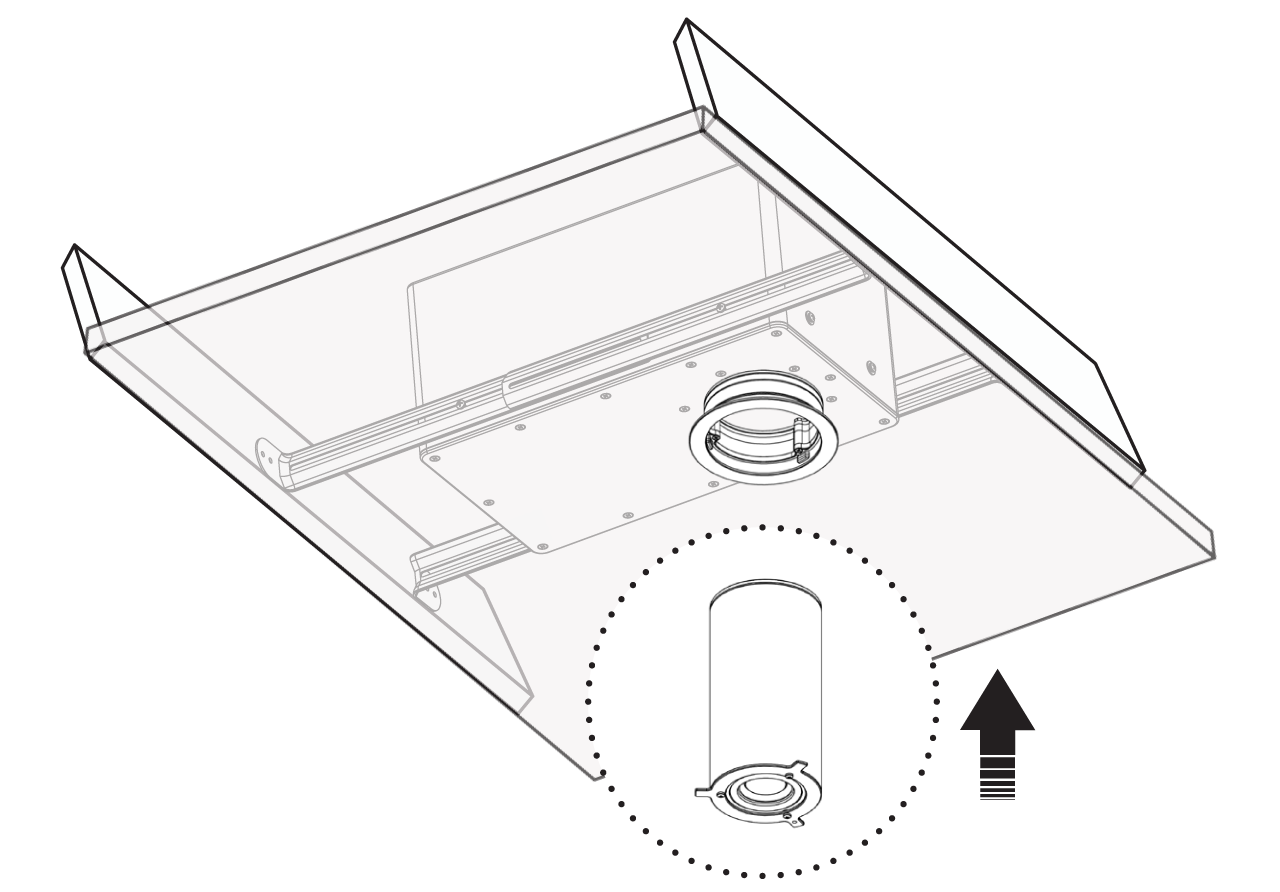
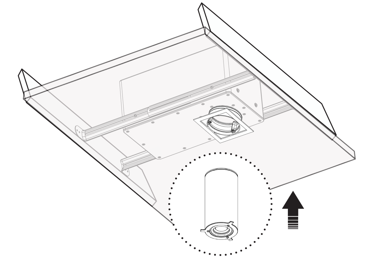
The MOS36MRM (Mid-Range Module) can now be inserted into the MOS36BOX Subwoofer assembly:
With Flanged Round Trim
With Flanged Square Trim
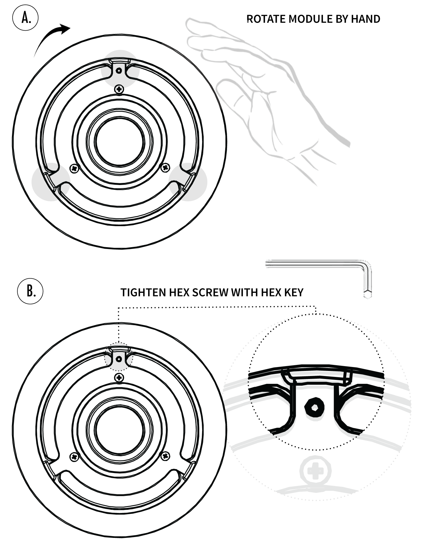
Rotate the MRM Module by hand, CLOCKWISE, until the three (3) metal wings rest inside the three (3) tabs of the Trim.
Finally, secure the MRM Module within the Subwoofer assembly using the provided Socket Head Screw and Hex Key.
Adding the Grille
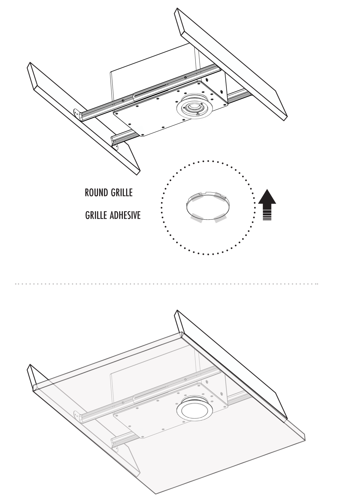
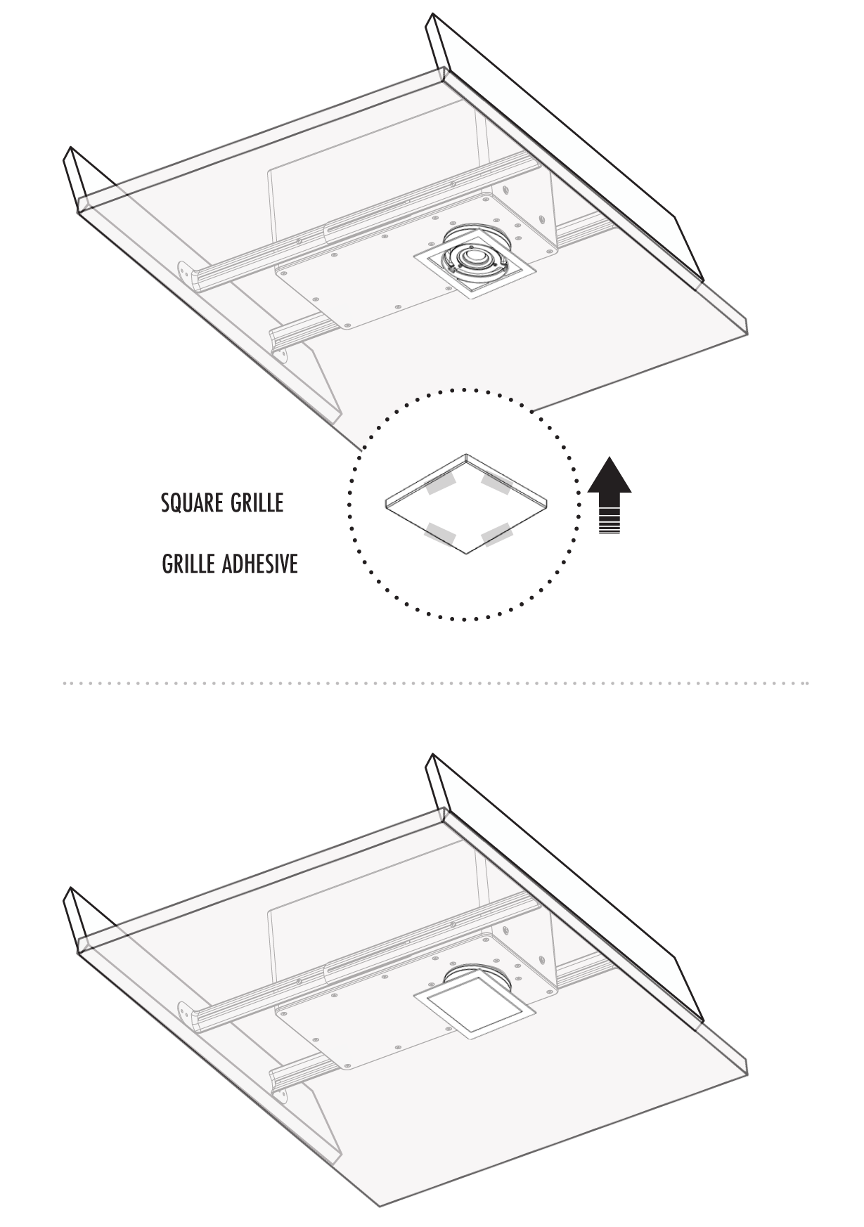
To complete the installation, use the pieces of included adhesive tack, to secure the press grille in place. The grille can be spray painted to better match the ceiling color and environment, prior to being attached.
Round Trim
Square Trim
Troubleshooting
If you have a problem, try isolating it first. For example, if you’re playing a DVD and there is no sound, try replacing the DVD with an MP3 player to see if you get sound. If it does work, then the problem is with the television, DVD player, or the cables connecting them. If it doesn’t work, the problem will be with the amplifier, speakers, or those cables.
Common Solutions
| PROBLEM | POSSIBLE CAUSES |
|---|---|
| NO SOUND | The volume may be turned down or muted. Check the volume settings volume may be turned down or muted. Check the volume settings on both the amplifier and the DVD player/ television/ computer/ etc. |
| NO SOUND | Make sure the proper source is selected on the amplifier or receiver. |
| NO SOUND | Check the cord connecting the amplifier with the source. The cord may be damaged or plugged into the wrong input or output. |
| NO SOUND | Check the wires connecting the amplifier with the speakers. Make sure they’re connected properly and not damaged in any way. |
| POOR SOUND QUALITY | If you hear something like static, or the sound is cutting in and out, check the audio cables. If the problem increases when a cable is being moved, then the cable is most likely faulty or not connected properly. |
| POOR SOUND QUALITY | Today’s audio systems may have several places to adjust the volume, for example your MP3 player may have a volume control, and your amplifier may also have one. Check to be certain that the volume isn’t turned up past 80% on any device. |
| POOR SOUND QUALITY | Try changing sources to be certain that the selection you’ve chosen is a good quality recording. |
Technical Assistance
If you have any questions or concerns about installing or using this product, you can reach us through one of the following methods:
Phone: (844) 674-4461
Hours of operation: 8:00am – 5:00pm (Pacific Time), Mon – Fri
Email: sales@originacoustics.com
If you are having technical trouble, please include the model number and briefly explain what steps you took to resolve the problem in your email, or be prepared to answer these questions over the phone. If you are considering returning the product, it’s required that you contact Origin Acoustics prior to any return attempts. This way we can determine if the issue can be resolved without returning the product, or if needed we can provide instructions and support for the return process.
Limited 5-Year Warranty
Origin Acoustics warrants to the original retail purchaser only that for a period of Five (5) years from the original date of purchase. This Origin Acoustics product will be free from defects in materials and workmanship, provided the speaker was purchased from an Origin Acoustics authorized dealer.
If the product is determined to be defective, it will be repaired or replaced at Origin Acoustics’ discretion. If the product must be replaced yet it is no longer manufactured, it will be replaced with a model of equal to or greater value that is the most similar to the original. If this is the case, installing the replacement model may require mounting modifications; Origin Acoustics will not be responsible for any such related costs.
Requirements & Coverage
This warranty may not be valid if the product was purchased through an unauthorized dealer. This warranty only applies to the individual that made the original purchase, and it cannot be applied to other purchases. The purchaser must be prepared to provide proof of purchase (receipt). This warranty will not be valid if the identifying number or serial number has been removed, defaced, or altered.
Not Covered by Warranty
- Accidental damage
- Damage caused by abuse or misuse
- Damage caused by attempted repairs/modifications by anyone other than Origin Acoustics or an authorized dealer
- Damage caused by improper installation
- Normal wear, maintenance, and environmental issues
- Damage caused by voltage inputs in excess of the rated maximum of the unit
- Damage inflicted during the return shipment
Return Process
Before making any return attempts, it is required that you first contact Origin Acoustics. Return product to Origin Acoustics or your dealer, either in person or by mail. It’s preferable if the product is returned in the original packaging. If this isn’t possible, the customer is responsible for insuring the shipment for the full value of the product.
This warranty is in lieu of all other expressed or implied warranties. Some states do not allow limitations on implied warranties, so this may not apply depending on the customer’s location. (For more information, see Magnuson-Moss Warranty Act.)
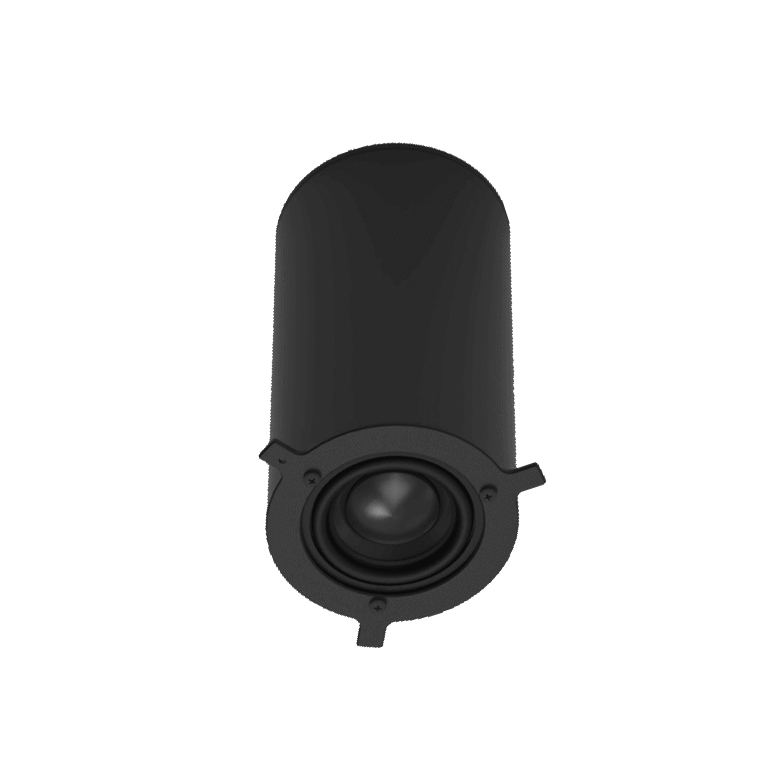
| MOS3600MRM | |
| Full Range Driver Components: | 2″ Wide Band Aluminum Cone Rubber Surround Neodymium Transducer |
| Diameter: | 2 ¹³⁄₁₆” (72 mm) |
| Height: | 5 ½” (14 mm) |
| Weight: | 0.55lbs (0.25kg) |
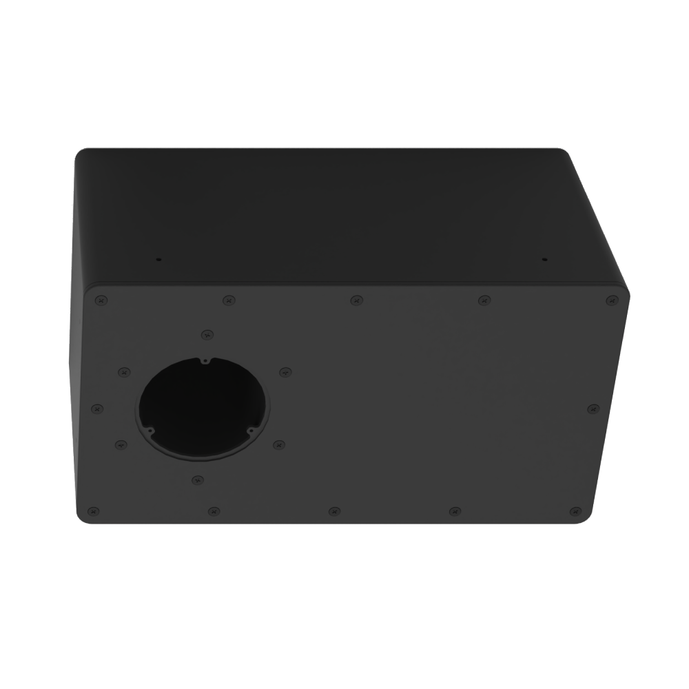
| MOS3600BOX | |
| Subwoofer: | 6½” Composite Glass Fiber |
| Enclosure: | Composite UL Resin |
| Mounting: | Overlapping Formed Steel Straps, Adjustable from 14.5″ – 22.5″ |
| Mounting Depth: | 6 ¾” (172 mm) |
| Width: |
8” (203 mm) |
| Length: |
14” (356 mm) |
| Weight: | 11.5lbs (5.23kg) |
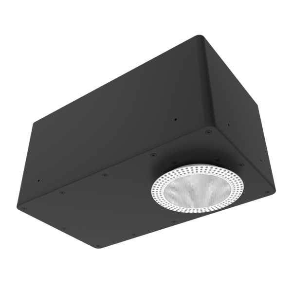
| MOS3600K | |
| System Type: | Two-Way Full Range Loudspeaker |
| Frequency Response: | 35Hz – 20kHz [ -10dB] 44Hz – 20kHz [ 3dB] |
| Power RMS: | 75 Watts |
| Power Peak: | 200 Watts 50W – 150W FTC @ 4 Ω |
| Recommended Crossover: | Custom Two-Way Passive 200Hz |
| Maximum SPL @ 1m: | 102 dB Continuous, 107 dB Peak |
| System coverage: | 100-degree conical |
| Sensitivity, 1W/1m: | 84 dB |
| Nominal Impedance: | 4 Ω |
| Input Connectors: | 2P Phoenix Connector |