InstaWidth™ Soundbar Collection Manual
Overview:
Install Guide:
Introduction
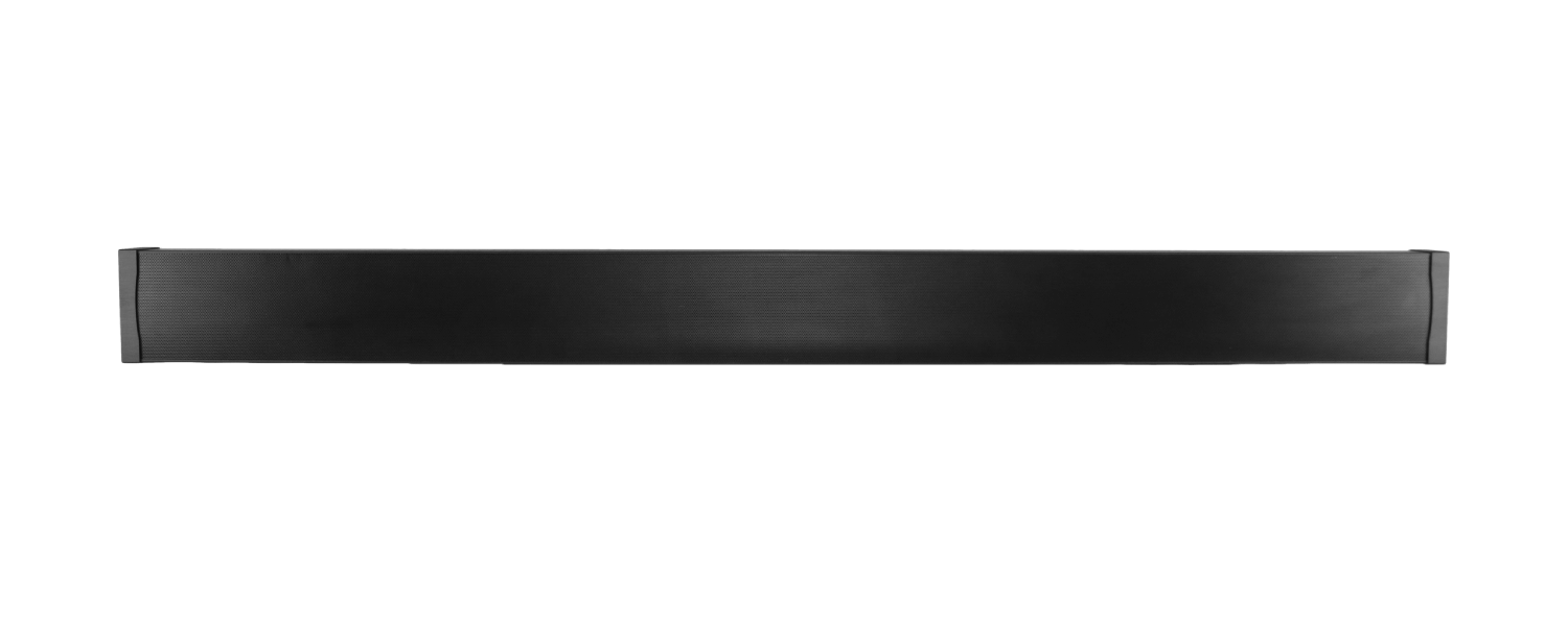
Thank you for choosing an Origin Soundbar. The Soundbar is a passive speaker system. The SBR41 & SBR41-LCR are single channel enclosures that can be placed on the Left, on the Right, or in the Center above & below the video display. Three speakers can also be placed in a linear row above or below the video display. The rest of the SBR43-50 to SBR43- 85 models contain all three channels, Left, Center and right.
The drivers are mounted in extruded aluminum enclosures and can be mounted on the wall or attached to a third-party mount connected directly to the video display. Regardless of your choice of mounting and position, the Soundbars will deliver pristine music and movie soundtracks and compliment your home theater experience.
This Soundbar range has been specially developed to extend and be adjusted in order to exact match any specific model of TV for the ideal visual symmetry within the space.
This instruction booklet cover the necessary information for a smooth installation, including: the tools you will need, step-by-step instructions for installation, troubleshooting tips for any errors that may occur, and all warranty information. If for any reason you experience problems or if you have installation questions please call us at (844) 674-4461. Hours of operation are 8:00am to 5:00pm (Pacific Time), Monday through Friday.
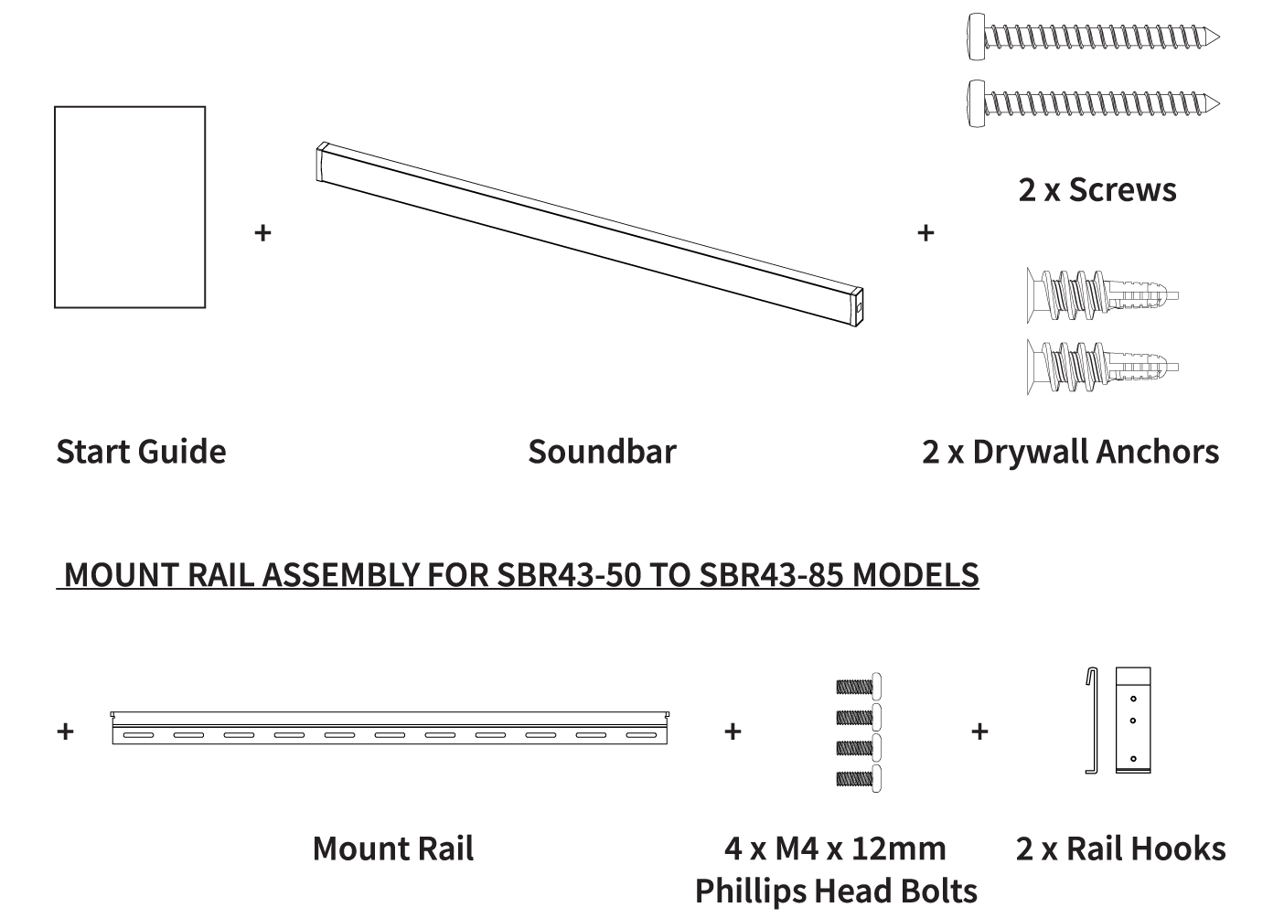
What’s Included
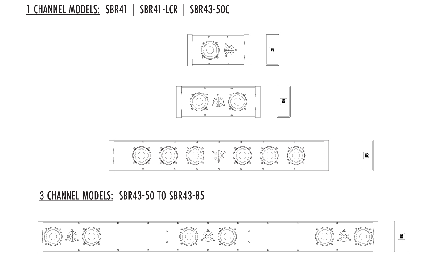
SBR41 & SBR41-LCR Mounting Steps
Firstly, determine the optimum position for mounting the Soundbar, based on the room parameters and your television location.
Care must be taken to ensure the soundbar is mounted securely.
It is best to check the angle of the television and use that line as a guide to avoid the appearance that the soundbar is mounted misaligned. Be advised that there are several relative angles in the room that may not be square. Use a level to establish the ideal position based on gravity.
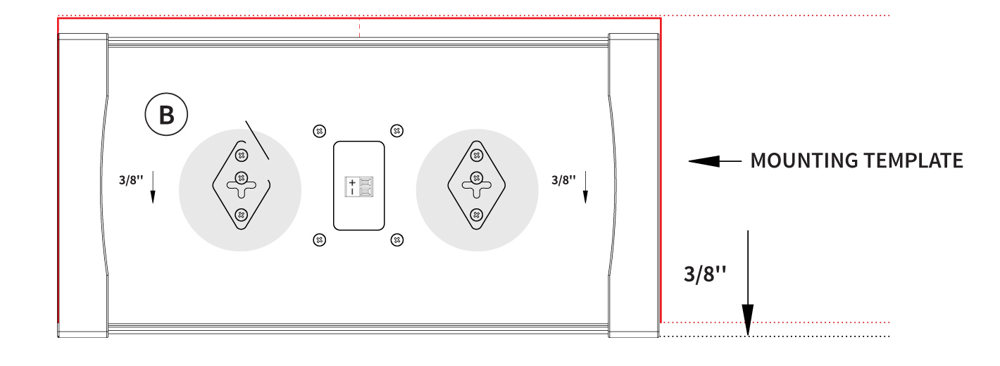
NOTE: The soundbars use a keyhole mounting system (See Diagrams 1, 2A & 2B).
The Soundbar will slide down 3/8” below the template location, until the screw rests at the uppermost position in the mounting element. Take this into account when marking screw holes.
Make sure there is enough room to accommodate the soundbar in the selected location.
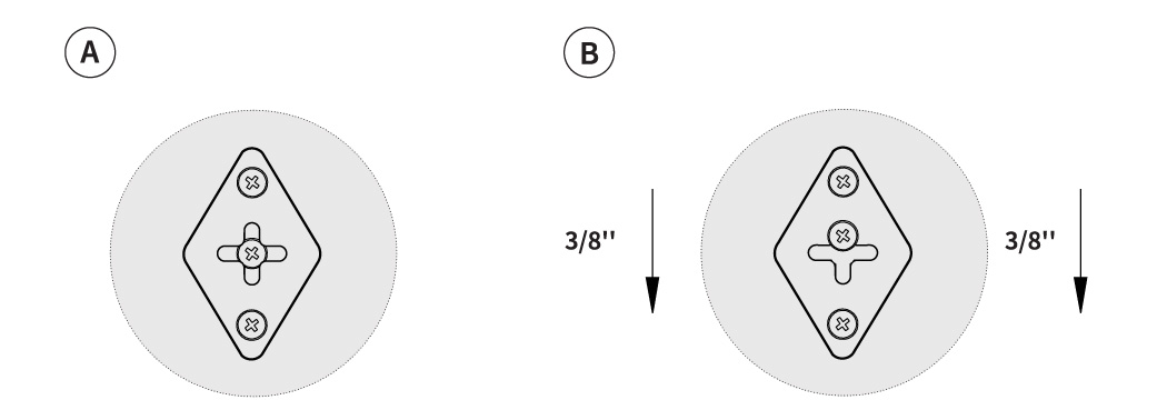
SOUNDBAR WILL SLIDE DOWN 3/8’’ BELOW THE SCREW HOLE LOCATION
Diagram 1.)
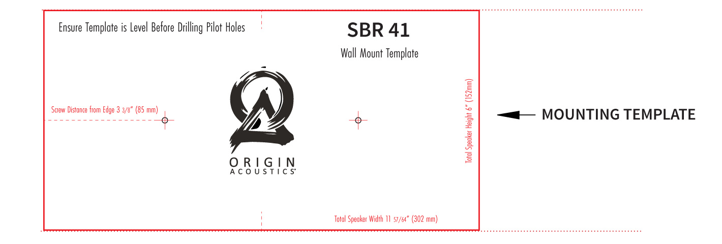
Diagram 2A.)
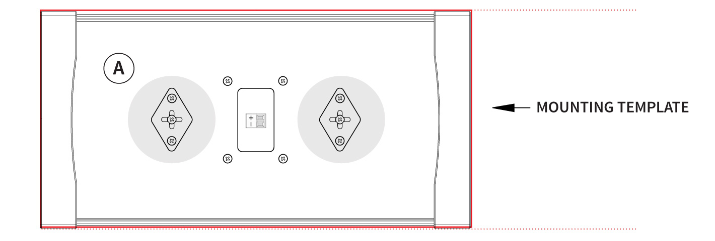
Diagram 2B.)
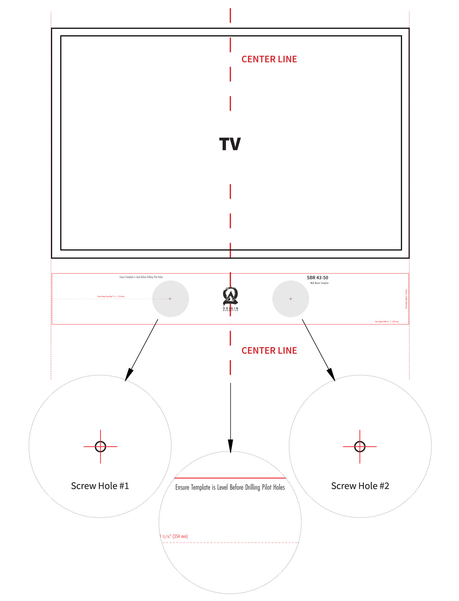
Once the position has been established, place the included template in the desired location (See Diagrams 3 & 4):
1. Making sure the position lines up with the television,
2. Secure the template with masking tape on the wall.
3. Mark the final screw position on the wall with a sharp tool or a tack.
4. Remove the template from the wall.
5. Drive in the screws using a screwdriver. Use the appropriate mounting: you will either use wood screws or drywall anchors to secure the soundbar behind the drywall.
6. Make sure when tightening the screws that enough space is allowed for the mounting element to slide over the head of the screw and into its final position. This may require a bit of adjustment to securely position the speaker against the wall. Once the mounting has been tested, remove the speaker from the wall. A hole must now be drilled into the wall to allow for the speaker wires to pass through, making sure the hole is large enough for all three wires to pass through. (See Diagrams 6 & 7)
Diagram 3.) SBR41 & SBR41-LCR MOUNTING OPTIONS
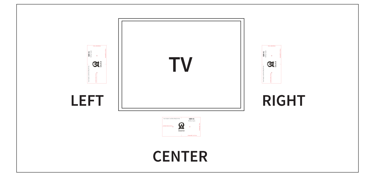
Diagram 4.) SBR43-41 & SBR41-LCR MOUNTING PLACEMENT
SBR43-50 to 43-85 Mounting Steps (w/ Mount Rail & Hooks)
The larger Soundbar models, SBR43-50 to SBR 43-85, cannot be screwed directly into the wall. The Soundbar must be supported by installing the included Mount Rail and 2 Rail Hooks.
MOUNTING RAIL HOOKS TO SOUND BAR
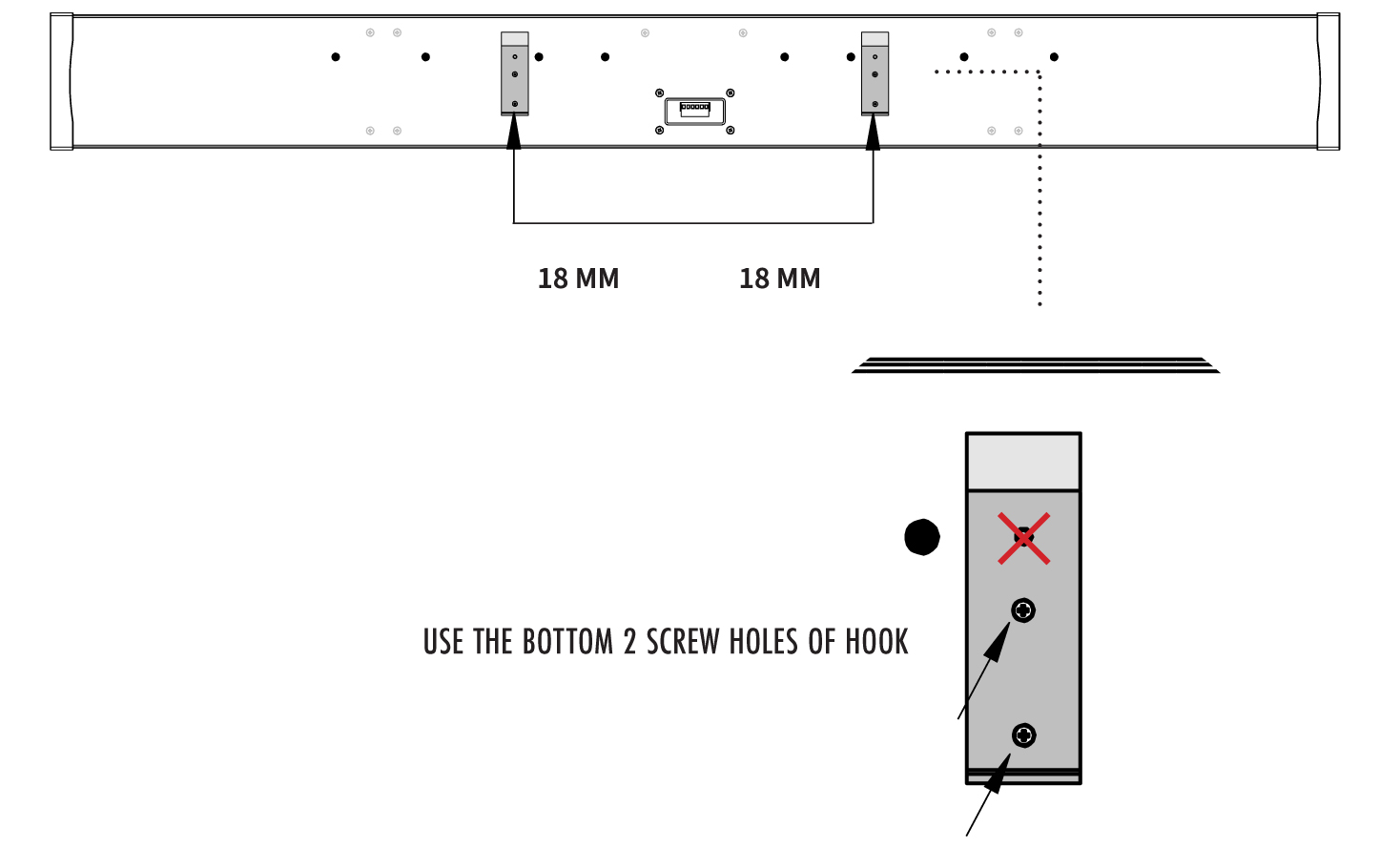
Firstly, identify the 4 small screws holes, each 4 mm in diameter, located 18mm from the center line on the back of the Soundbar.
Use the included M4 x 12mm Phillips Bolts to attach the 2 Rail Hooks to the Soundbar, into these 4 small screw holes (See Diagrams 5A, B and C). Ensure the bottom two screw holes of the Rail Hook are used [The top third screw hole is not used].
Diagram 5A.) ATTACHING RAIL HOOKS TO SBR43-50 TO SBR43-85
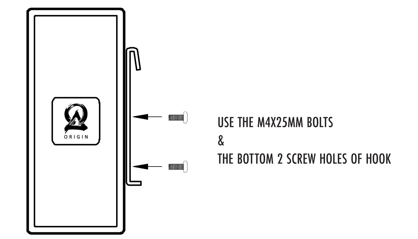
Diagram 5B.) ATTACHING RAIL HOOKS TO SBR43-50 TO SBR43-85
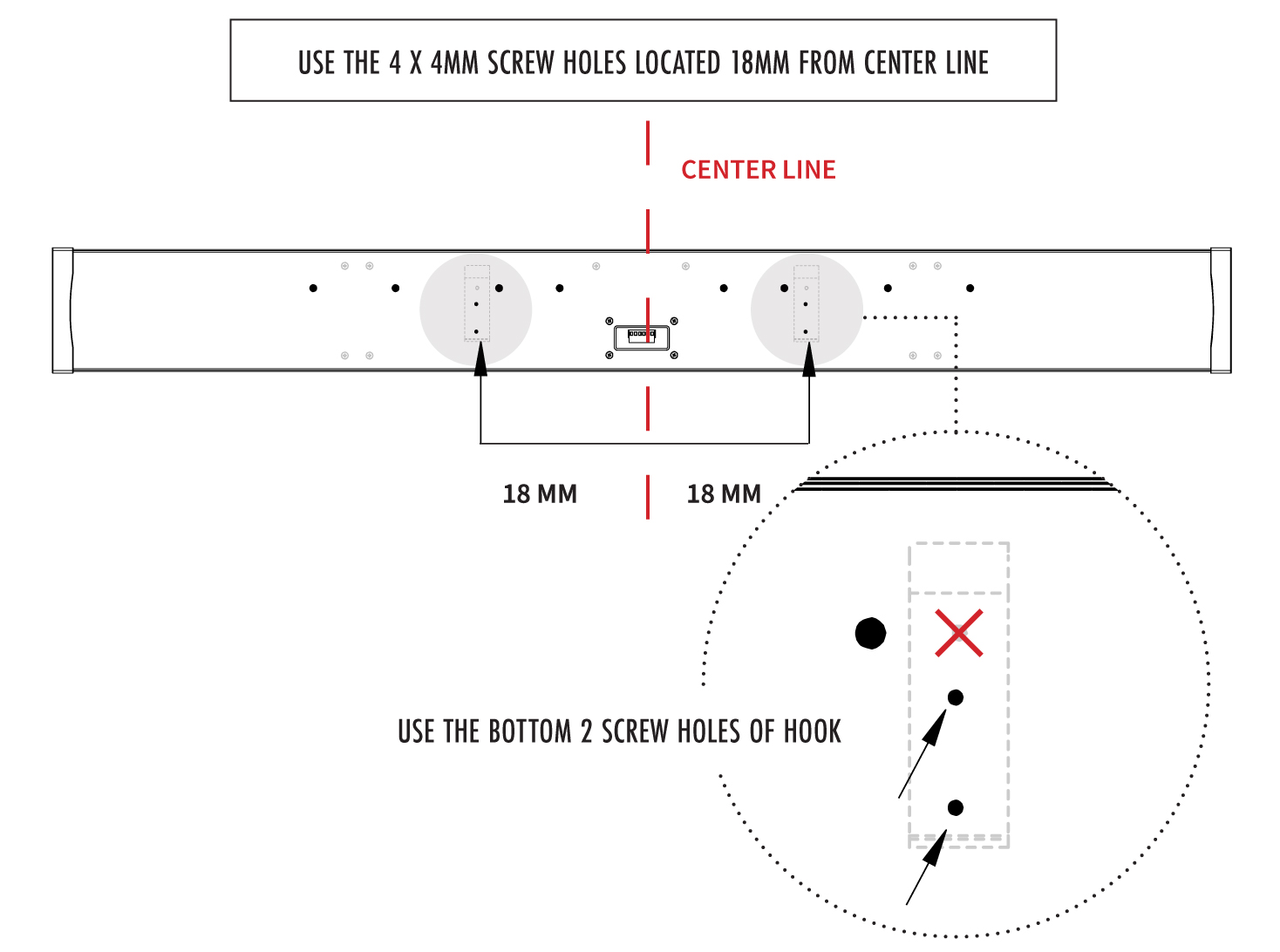
Diagram 5C.) ATTACHING RAIL HOOKS TO SBR43-50 TO SBR43-85
ATTACHING MOUNT RAIL TO WALL
Now locate the best placement for the Mount Rail on the wall, by following the same instructions as the smaller SBR models.
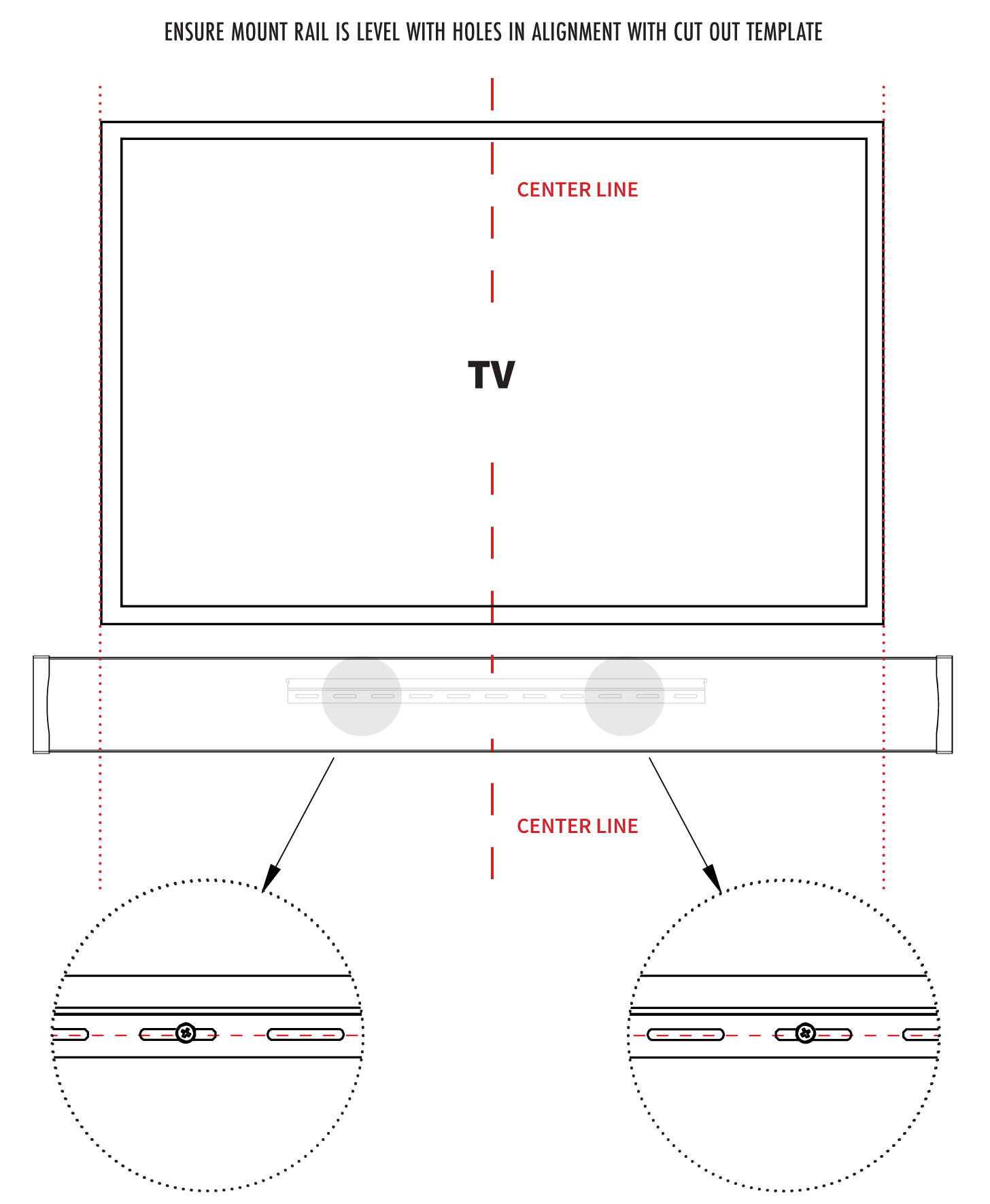
Using a level, align the Cut-Out Template to the TV, and locate the height for the 2 screw holes to mount the Mount Rail to the wall. Use a pencil to mark these screw locations.
Use the appropriate mounting to mount the Mount Rail: either wood screws or drywall anchors to secure the soundbar on drywall, through the Mount Rail Holes, ensuring the Mount Rail Holes are in contact and touching the wall (See Diagram 6A). Remember the location of these 2 screws for the Mount Rail will be 2” below the top of the final mounted Soundbar (See Diagram 6B).
Diagram 6A.) ATTACHING RAIL HOOKS TO SBR43-50 TO SBR43-85
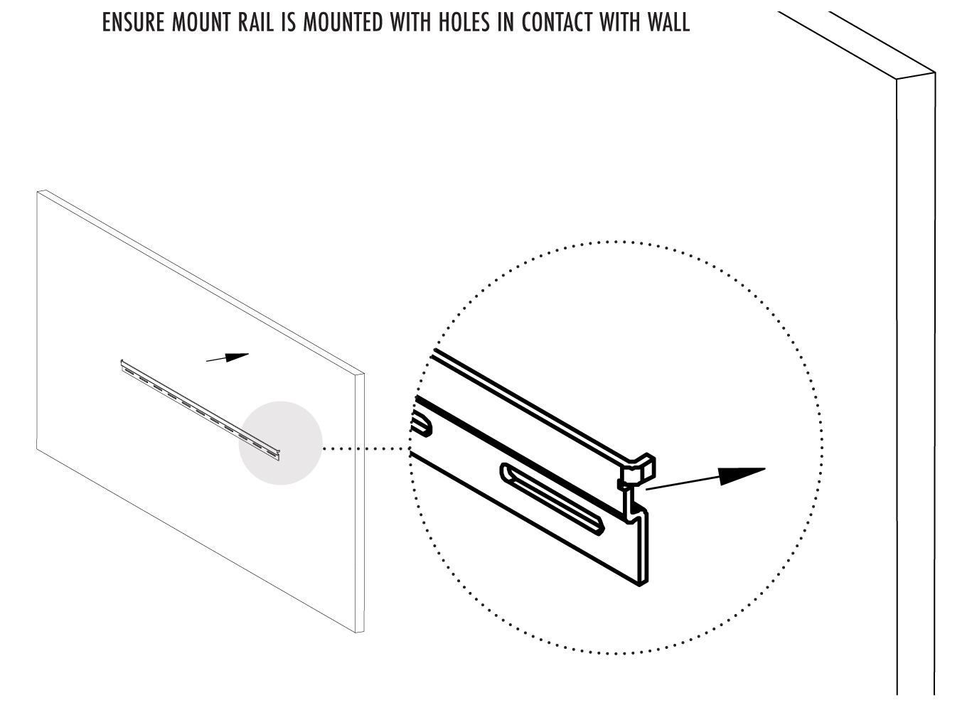
Diagram 6B.) ATTACHING RAIL HOOKS TO SBR43-50 TO SBR43-85
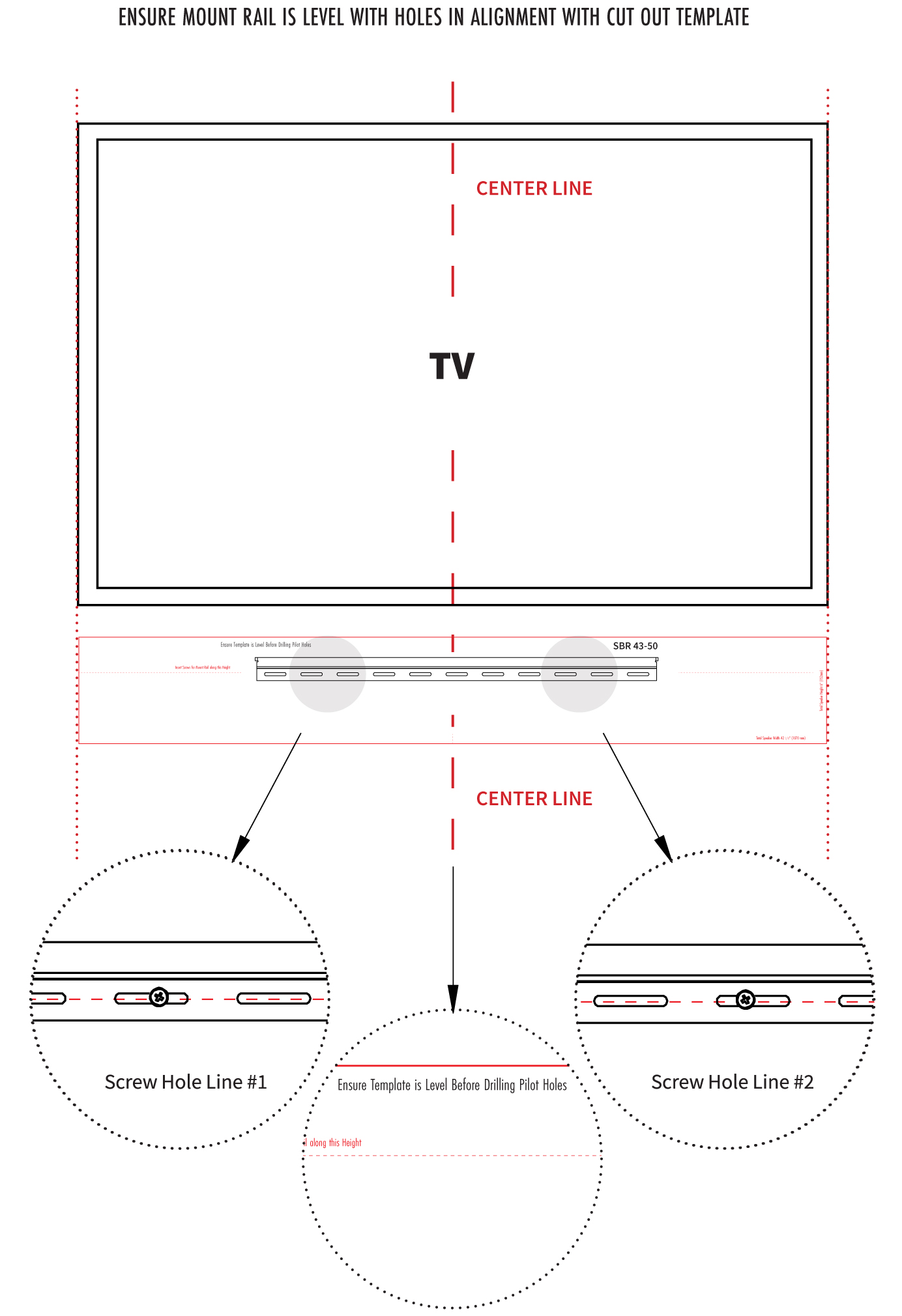
Diagram 6C.) HOOKING SOUNDBAR TO MOUNTING RAIL
Once the Mount Rail is correctly positioned & securely mounted to the wall, simply attach the Soundbar by hooking the Rail Hooks over the Mount Rail.
Diagram 7A.) HOOKING SOUNDBAR TO MOUNTING RAIL
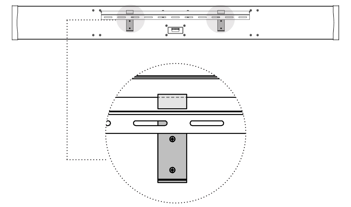
Diagram 7B.) HOOKING SOUNDBAR TO MOUNTING RAIL
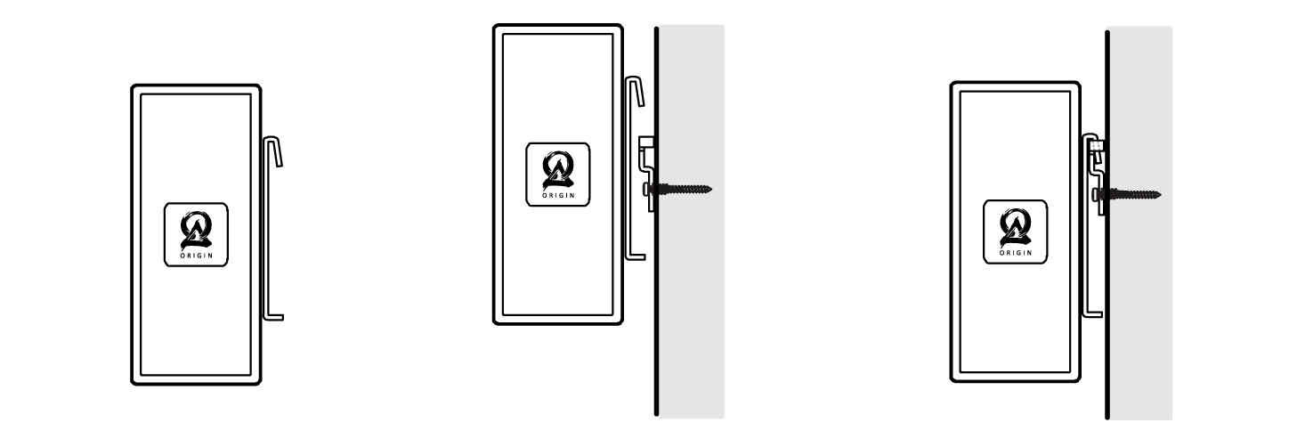
Diagram 7C.) HOOKING SOUNDBAR TO MOUNTING RAIL
Extending the Soundbar to Match TV Length
To perfectly align to the TV length, each soundbar can be extended by 1”, before securing to the wall. This is done by extending the screw caps by up to 1/2 inch on each end of the soundbar. Make sure to center the screws on the wall before you prepare to extend the soundbar. Take off the logo-engraved magnetic cover, on each end-cap, and use a drill, to loosen the two screws on each end of the Soundbar.
Making Small Length Adjustments:
1. Once the logo-engraved cover is off (See Diagram 8), use a drill with a Phillips head, anticlockwise, to loosen & extend the soundbar end-cap. Several possible adjustments can be made to provide the best match to the exact TV length.
2. Alternate adjustments between the 2 screws, to make sure the angles of the end caps stay parallel.
3. Once extended fully, each end cap will reach an additional 1/2”, if a longer length adjustment is desired, take off the second end cap, and repeat the process to reach an additional 1/2” length in size.
To shorten the length, use the drill, clockwise, to re-righten the cap.
Diagram 8.)
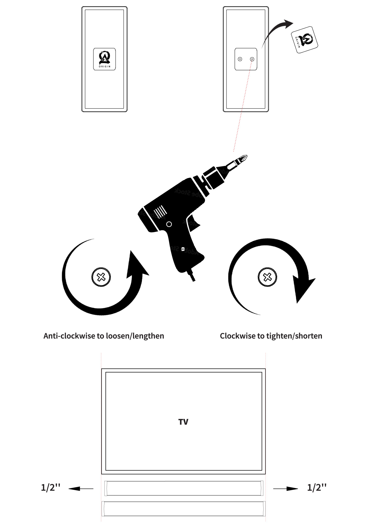
Diagram 9.) SBR41 & SBR41-LCR WIRING OPTIONS
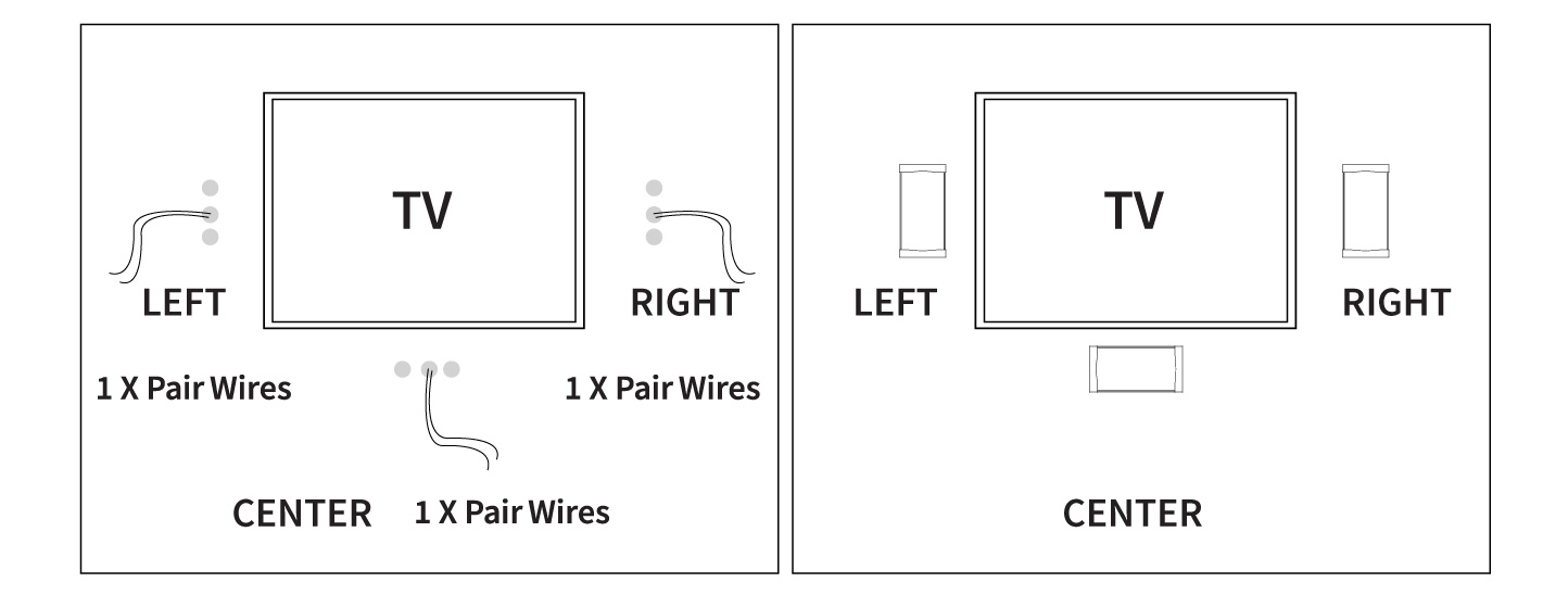
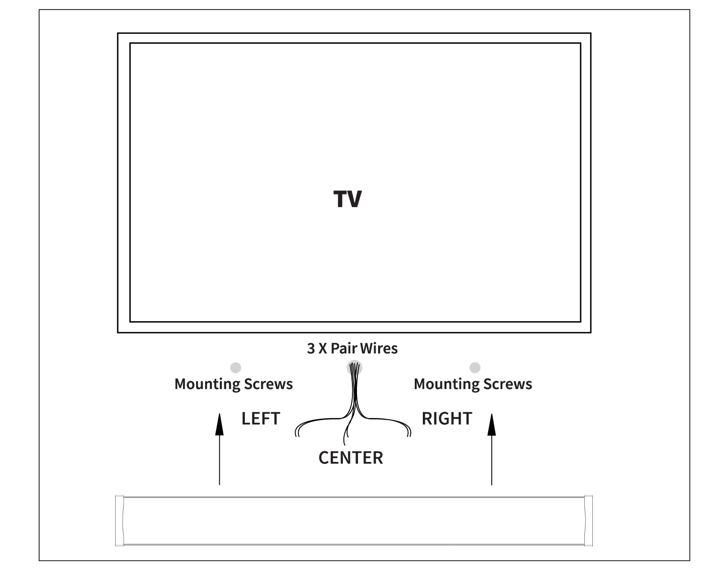
Diagram 10.) SBR43-50 TO SBR43-85 WIRING
Wiring Connection
Once the mounting screws are installed and the wire hole has been drilled, it is time to run the wires.
Each soundbar will have an individual pair of speaker wires for each speaker:
Diagram 9.) The SBR41 & SBR41-LCR models will have 1 pair of wires to connect to the single speaker, and can be mounted each as either a Left, Center, or Right speaker.
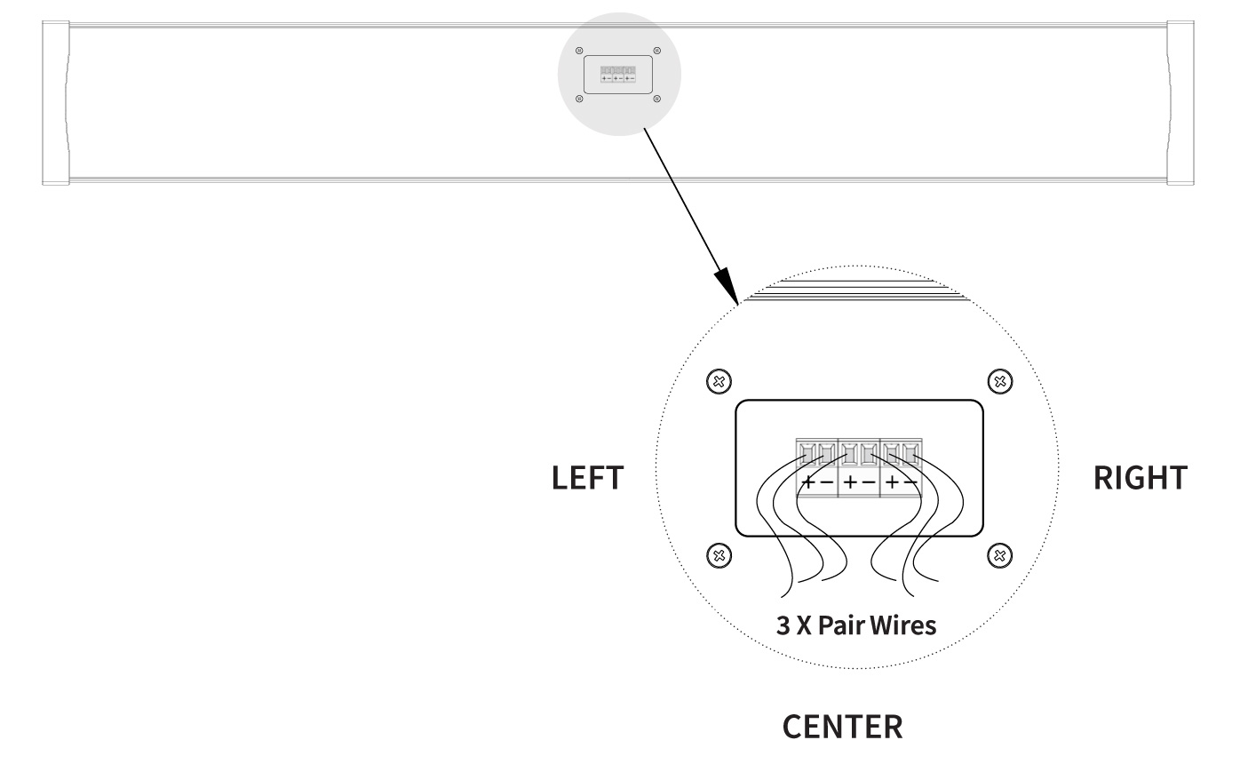
Diagram 10.) The SBR43-50 – SBR43-85 range of models will have 3 pairs of wires to connect to the each of their 3 internal speakers.
Each pair of speaker wires will have a positive (+) and negative (-) connection. Check your speaker wire for the indication along the wire to differentiate between the two. Make sure you use the same wire to connect to (+) and (-) on both the speaker and the amplifier/receiver.
Strip the insulation ½’’ from the end of the wire. Run the speakers out of the hole in the wall and use the connectors to attach the correct wires to the speaker terminals. The terminals operate by putting the wire inside the terminal. After the wire is inserted, use a screwdriver to turn the screw, and it will lock the wire in place. Lastly, make sure the insulation is not inserted into the hole in the terminal as it will not allow the wire to make a connection.
NOTE: On the SBR41 & SBR41-LCR models, ensure you connect the appropriate channel, Left, Center and Right, on both the speaker and the amplifier/receiver. If not, the positional steering of the movie soundtrack will be incorrect. (See Diagram 11).
Diagram 11a.) SBR41 & SBR41-LCR WIRING WITH SINGLE PHOENIX CONNECTOR
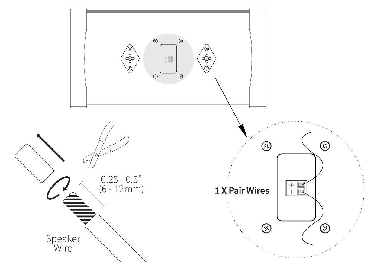
Diagram 11b.) SBR43-50 TO SBR43-85 WIRING WITH 3-PIN PHOENIX CONNECTOR
Finalizing the Installation
Once the speaker has been wired, secure the Soundbar to the wall by sliding it over the screws. Make sure to feed the wires into the wall as you prepare to mount it to avoid pinching, kinking or disconnection during the mounting process. Your new Soundbar is now ready for your listening enjoyment.
Perfecting the Sound
Depending on the complexity of your system, there are several possible adjustments to provide the best possible sonic experience:
Most audio/video receivers (AVR’s) have some type of test program that plays a signal through each channel to allow you to balance the output. This is best performed from the principle listening position.
There will also be equalization (EQ) controls to adjust the frequency response as it is effected by the parameters of the room.
If you are using a dedicated subwoofer, adjusting the balance and crossover point between the subwoofer and your Soundbar is critical; the ideal balance will provide deep warm bass without overshadowing the mids and highs that are so critical in a musical performance. This may take a few days and several small adjustments to get it right.
Lastly, be aware that different sources, BluRay Disc Players, Cable TV, streaming music will all have slightly different volume levels and EQ curves. Even different television channels may vary in their sonic presentation. This is normal and something you can adjust to your preference.
Troubleshooting
If you have a problem, try isolating it first. For example, if you’re playing a DVD and there is no sound, try replacing the DVD with an MP3 player to see if you get sound. If it does work, then the problem is with the television, DVD player, or the cables connecting them. If it doesn’t work, the problem will be with the amplifier, speakers, or those cables.
Common Solutions
| PROBLEM | POSSIBLE CAUSES |
|---|---|
| NO SOUND | The volume may be turned down or muted. Check the volume settings volume may be turned down or muted. Check the volume settings on both the amplifier and the DVD player/ television/ computer/ etc. |
| NO SOUND | Make sure the proper source is selected on the amplifier or receiver. |
| NO SOUND | Check the cord connecting the amplifier with the source. The cord may be damaged or plugged into the wrong input or output. |
| NO SOUND | Check the wires connecting the amplifier with the speakers. Make sure they’re connected properly and not damaged in any way. |
| POOR SOUND QUALITY | If you hear something like static, or the sound is cutting in and out, check the audio cables. If the problem increases when a cable is being moved, then the cable is most likely faulty or not connected properly. |
| POOR SOUND QUALITY | Today’s audio systems may have several places to adjust the volume, for example your MP3 player may have a volume control, and your amplifier may also have one. Check to be certain that the volume isn’t turned up past 80% on any device. |
| POOR SOUND QUALITY | Try changing sources to be certain that the selection you’ve chosen is a good quality recording. |
Technical Assistance
If you have any questions or concerns about installing or using this product, you can reach us through one of the following methods:
Phone: (844) 674-4461
Hours of operation: 8:00am – 5:00pm (Pacific Time), Mon – Fri
Email: sales@originacoustics.com
If you are having technical trouble, please include the model number and briefly explain what steps you took to resolve the problem in your email, or be prepared to answer these questions over the phone. If you are considering returning the product, it’s required that you contact Origin Acoustics prior to any return attempts. This way we can determine if the issue can be resolved without returning the product, or if needed we can provide instructions and support for the return process.
Limited 5-Year Warranty
Origin Acoustics warrants to the original retail purchaser only that this Origin Acoustics product will be free from defects in materials and workmanship, provided the speaker was purchased from an Origin Acoustics authorized dealer.
If the product is determined to be defective, it will be repaired or replaced at Origin Acoustics’ discretion. If the product must be replaced yet it is no longer manufactured, it will be replaced with a model of equal to or greater value that is the most similar to the original. If this is the case, installing the replacement model may require mounting modifications; Origin Acoustics will not be responsible for any such related costs.
Requirements & Coverage
This warranty may not be valid if the product was purchased through an unauthorized dealer. This warranty only applies to the individual that made the original purchase, and it cannot be applied to other purchases. The purchaser must be prepared to provide proof of purchase (receipt). This warranty will not be valid if the identifying number or serial number has been removed, defaced, or altered.
Not Covered by Warranty
- Accidental damage
- Damage caused by abuse or misuse
- Damage caused by attempted repairs/modifications by anyone other than Origin Acoustics or an authorized dealer
- Damage caused by improper installation
- Normal wear, maintenance, and environmental issues
- Damage caused by voltage inputs in excess of the rated maximum of the unit
- Damage inflicted during the return shipment
Return Process
Before making any return attempts, it is required that you first contact Origin Acoustics. Return product to Origin Acoustics or your dealer, either in person or by mail. It’s preferable if the product is returned in the original packaging. If this isn’t possible, the customer is responsible for insuring the shipment for the full value of the product.
This warranty is in lieu of all other expressed or implied warranties. Some states do not allow limitations on implied warranties, so this may not apply depending on the customer’s location. (For more information, see Magnuson-Moss Warranty Act.)

| SBR41 | |
| Part: | SBR41000 |
| Channels: | 1 |
| Woofers: | 1 x 3 ½” Fiber Glass |
| Tweeter: | 1 x 1” Silk DPSD™ |
| Frequency Response: | 65Hz – 20kHz |
| Impedance: | 4 Ω per Channel |
| Power RMS: | 75 Watts |
| Power Peak: | 150 Watts |
| Sensitivity: | 90 dB |
| Enclosure: | Aluminum Cabinet |
| Height & Depth: | 6’’ H x 2⁹⁄₁₆’’ D (152 H x 65 D mm) |
| Length: | 11⅞” – 12⅞” [302 – 327 mm] |
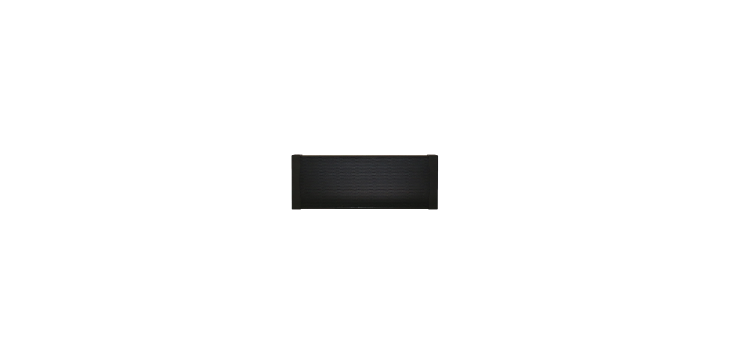
| SBR41-LCR | |
| Part: | SBR41LCR |
| Channels: | 1 |
| Woofers: | 2 x 3 ½” Fiber Glass |
| Tweeter: | 1 x 1” Silk DPSD™ |
| Frequency Response: | 65Hz – 20kHz |
| Impedance: | 4 Ω per Channel |
| Power RMS: | 75 Watts |
| Power Peak: | 150 Watts |
| Sensitivity: | 90 dB |
| Enclosure: | Aluminum Cabinet |
| Height & Depth: | 6’’ H x 2⁹⁄₁₆’’ D (152 H x 65 D mm) |
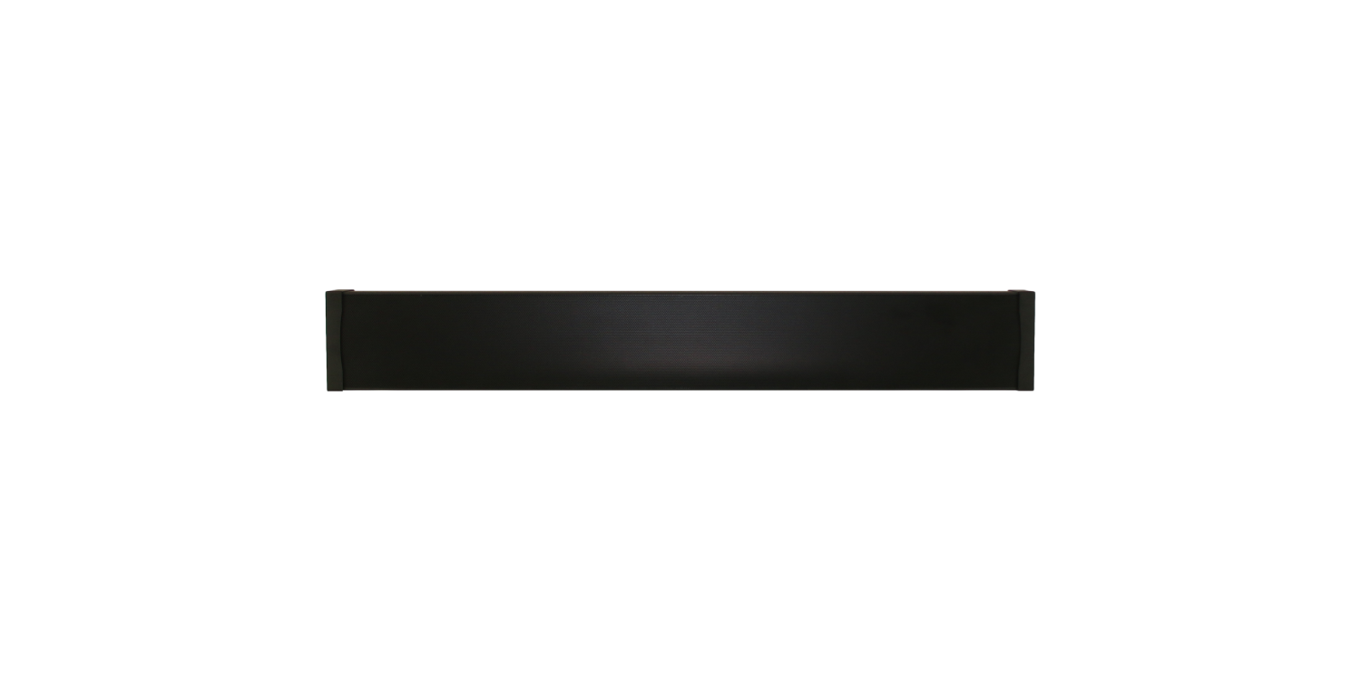
| Length: | 16¹⁄₁₆” – 17¹⁄₁₆” [409 – 434 mm] |
| SBR43-50 | |
| Part: | SBR43500 |
| Channels: | 3 |
| Woofers: | 2 x 3 ½” Fiber Glass |
| Tweeter: | 1 x 1” Silk DPSD™ |
| Frequency Response: | 65Hz – 20kHz |
| Impedance: | 4 Ω per Channel |
| Power RMS: | 75 Watts |
| Power Peak: | 150 Watts |
| Sensitivity: | 90 dB |
| Enclosure: | Aluminum Cabinet |
| Height & Depth: | 6’’ H x 2⁹⁄₁₆’’ D (152 H x 65 D mm) |
| Length: | 42¹⁄₁₆” – 43¹⁄₁₆” [1070 – 1095 mm] |

| SBR43-50C | |
| Part: | SBR4350C |
| Channels: | 1 |
| Woofers: | 2 x 3 ½” Fiber Glass |
| Tweeter: | 1 x 1” Silk DPSD™ 4 x passive radiators |
| Frequency Response: | 65Hz – 20kHz |
| Impedance: | 4 Ω per Channel |
| Power RMS: | 75 Watts |
| Power Peak: | 150 Watts |
| Sensitivity: | 90 dB |
| Enclosure: | Aluminum Cabinet |
| Height & Depth: | 6’’ H x 2⁹⁄₁₆’’ D (152 H x 65 D mm) |
| Length: | 42¹⁄₁₆” – 43¹⁄₁₆” [1070 – 1095 mm] |
| SBR43-55 | |
| Part: | SBR43550 |
| Channels: | 3 |
| Woofers: | 6 x 3 ½’ Fiber Glass |
| Tweeter: | 3 x 1” Silk DPSD™ |
| Frequency Response: | 65Hz – 20kHz |
| Impedance: | 4 Ω per Channel |
| Power RMS: | 75 Watts |
| Power Peak: | 150 Watts |
| Sensitivity: | 90 dB |
| Enclosure: | Aluminum Cabinet |
| Height & Depth: | 6’’ H x 2⁹⁄₁₆’’ D (152 H x 65 D mm) |
| Length: | 48³⁄₁₆” – 49³⁄₁₆” [1225 – 1250 mm] |
| SBR43-60 | |
| Part: | SBR43600 |
| Channels: | 3 |
| Woofers: | 6 x 3 ½” Fiber Glass |
| Tweeter: | 3 x 1” Silk DPSD™ |
| Frequency Response: | 65Hz – 20kHz |
| Impedance: | 4 Ω per Channel |
| Power RMS: | 75 Watts |
| Power Peak: | 150 Watts |
| Sensitivity: | 90 dB |
| Enclosure: | Aluminum Cabinet |
| Height & Depth: | 6’’ H x 2⁹⁄₁₆’’ D (152 H x 65 D mm) |
| Length: | 52⅝” – 53⅝” [1339 – 1364 mm] |
| SBR43-65 | |
| Part: | SBR43650 |
| Channels: | 3 |
| Woofers: | 6 x 3 ½’ Fiber Glass |
| Tweeter: | 3 x 1” Silk DPSD™ |
| Frequency Response: | 65Hz – 20kHz |
| Impedance: | 4 Ω per Channel |
| Power RMS: | 75 Watts |
| Power Peak: | 150 Watts |
| Sensitivity: | 90 dB |
| Enclosure: | Aluminum Cabinet |
| Height & Depth: | 6’’ H x 2⁹⁄₁₆’’ D (152 H x 65 D mm) |
| Length: | 56⁷⁄₁₆” – 57⁷⁄₁₆” [1435 – 1460 mm] |
| SBR43-70 | |
| Part: | SBR43700 |
| Channels: | 3 |
| Woofers: | 6 x 3 ½” Fiber Glass |
| Tweeter: | 3 x 1” Silk DPSD™ |
| Frequency Response: | 65Hz – 20kHz |
| Impedance: | 4 Ω per Channel |
| Power RMS: | 75 Watts |
| Power Peak: | 150 Watts |
| Sensitivity: | 90 dB |
| Enclosure: | Aluminum Cabinet |
| Height & Depth: | 6’’ H x 2⁹⁄₁₆’’ D (152 H x 65 D mm) |
| Length: | 60¾” – 61¾” [1545 – 1570 mm] |
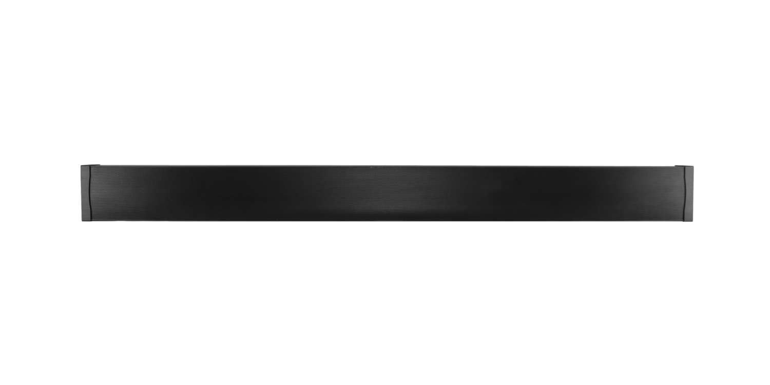
| SBR43-75 | |
| Part: | SBR43750 |
| Channels: | 3 |
| Woofers: | 6 x 3 ½” Fiber Glass |
| Tweeter: | 3 x 1” Silk DPSD™ |
| Frequency Response: | 65Hz – 20kHz |
| Impedance: | 4 Ω per Channel |
| Power RMS: | 75 Watts |
| Power Peak: | 150 Watts |
| Sensitivity: | 90 dB |
| Enclosure: | Aluminum Cabinet |
| Height & Depth: | 6’’ H x 2⁹⁄₁₆’’ D (152 H x 65 D mm) |
| Length: | 65⅛” – 66⅛” [1654 – 1680 mm] |
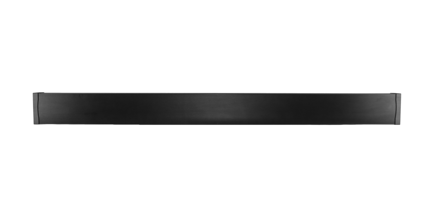
| SBR43-80 | |
| Part: | SBR43800 |
| Channels: | 3 |
| Woofers: | 6 x 3 ½” Fiber Glass |
| Tweeter: | 3 x 1” Silk DPSD™ |
| Frequency Response: | 65Hz – 20kHz |
| Impedance: | 4 Ω per Channel |
| Power RMS: | 75 Watts |
| Power Peak: | 150 Watts |
| Sensitivity: | 90 dB |
| Enclosure: | Aluminum Cabinet |
| Height & Depth: | 6’’ H x 2⁹⁄₁₆’’ D (152 H x 65 D mm) |
| Length: | 69⁷⁄₁₆” – 70⁷⁄₁₆” [1765 – 1790 mm] |
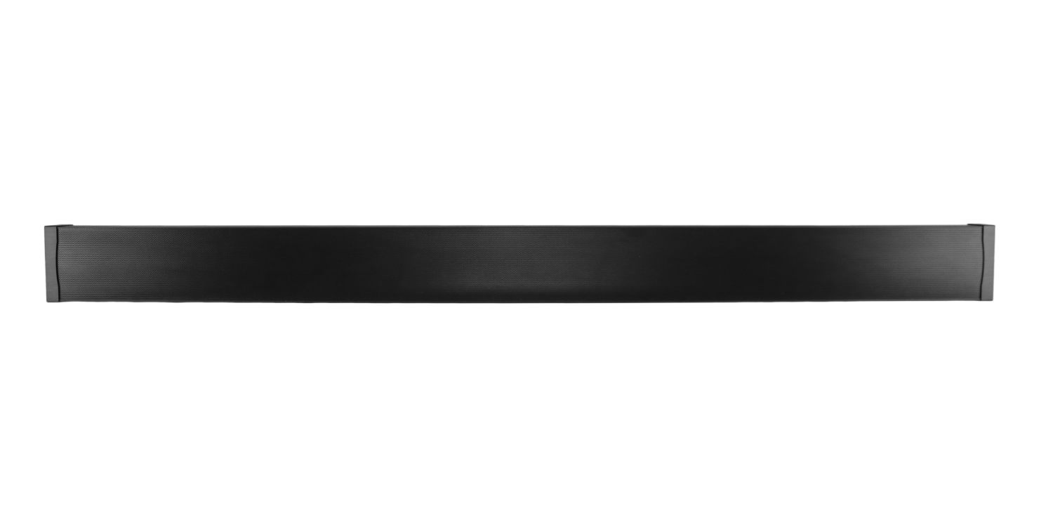
| SBR43-85 | |
| Part: | SBR43850 |
| Channels: | 3 |
| Woofers: | 6 x 3 ½” Fiber Glass |
| Tweeter: | 3 x 1” Silk DPSD™ |
| Frequency Response: | 65Hz – 20kHz |
| Impedance: | 4 Ω per Channel |
| Power RMS: | 75 Watts |
| Power Peak: | 150 Watts |
| Sensitivity: | 90 dB |
| Enclosure: | Aluminum Cabinet |
| Height & Depth: | 6’’ H x 2⁹⁄₁₆’’ D (152 H x 65 D mm) |
| Length: | 73¹⁵⁄₁₆” – 74¹⁵⁄₁₆” [1880 – 1905 mm] |