SUBS10 Slim Subwoofer Manual
Overview:
Install Guide:
Introduction
Thank you for choosing the SUBS10 Slim Subwoofer. At Origin Acoustics, we take pride in providing you with a high-quality product. All of Origin Acoustics’ speakers are designed to have excellent sound quality, longevity, and a simple installation process.
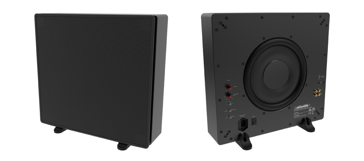
This Subwoofer has been specially developed to provide resounding bass through a modern & compact design, allowing it to seamlessly fit the visual symmetry of any interior space.
This instruction booklet covers the necessary information for a smooth installation, including: the tools you will need, step-by-step instructions for installation, troubleshooting tips for any errors that may occur, and all warranty information. If for any reason you experience problems or if you have installation questions please call us at (844) 674-4461. Hours of operation are 8:00am to 5:00pm (Pacific Time), Monday through Friday.
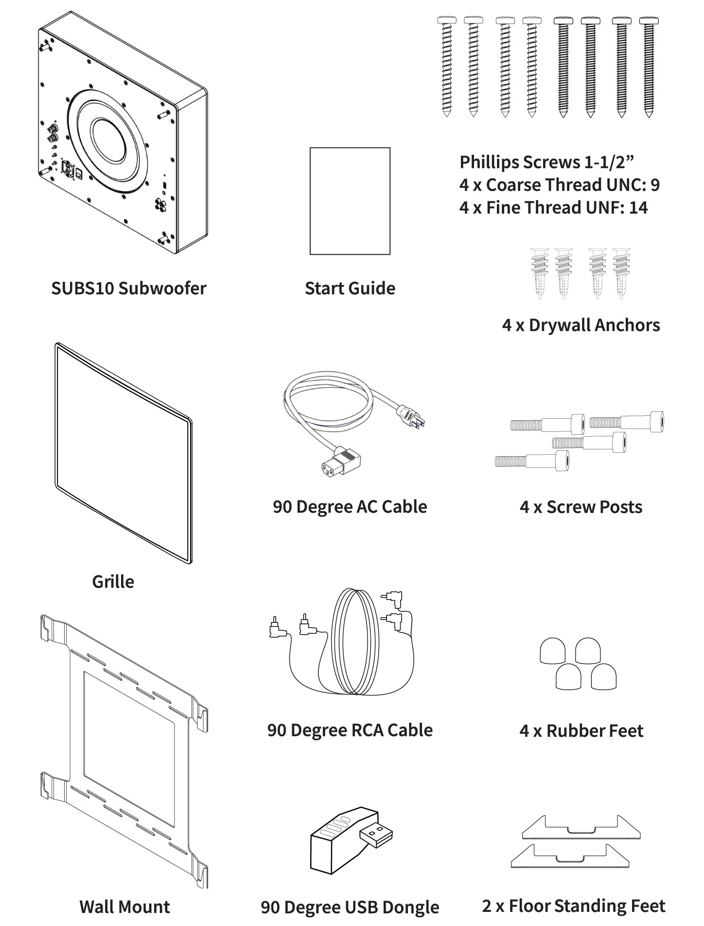
What’s Included
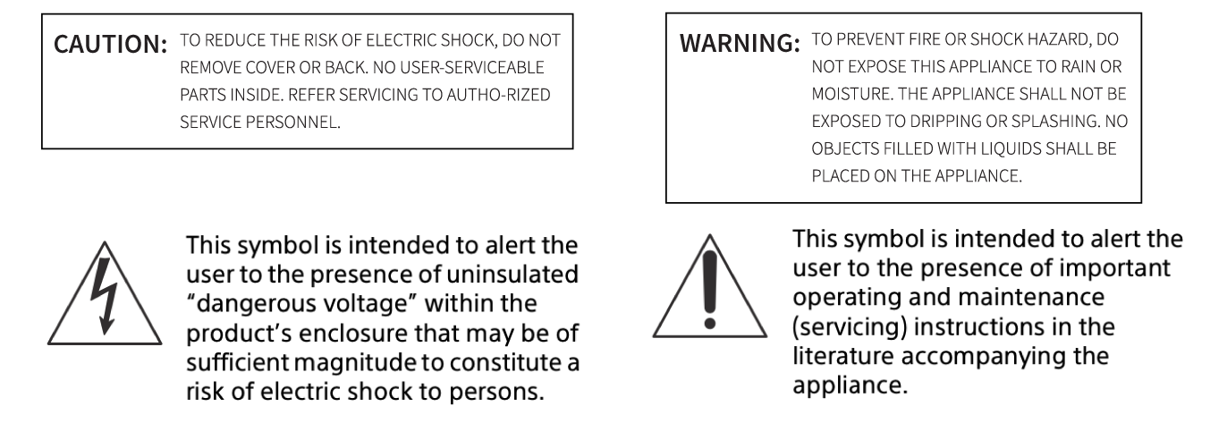
WARNING
To reduce the risk of fire or electric shock, do not expose this apparatus to rain or moisture.
To reduce the risk of fire, do not cover the ventilation opening of the appliance with newspapers, tablecloths, curtains, etc, Do not expose the appliance to naked flame sources (for example, lighted candles)
To reduce the risk of fire or electric shock, do not expose this appliance to dripping or splashing, and do not place objects filled with liquids, such as vases, on the appliance.
Do not install the appliance in a confined space, such as a bookcase or built-in cabinet.
As the main plug is used to disconnect the unit from the mains, connect the unit to an easily accessible AC outlet. Should you notice an abnormality in the unit, disconnect the main plug from the AC outlet immediately.
The unit is not disconnected from the mains as long as it is connected to the AC outlet, even if the unit itself has been turned off.
IMPORTANT SAFETY INSTRUCTIONS
1.) Read these instructions
2.) Keep these instructions
3.) Heed all warnings
4.) Follow all instructions
5.) Do not use apparatus near water
6.) Clean only with a dry cloth
7.) Do not block any ventilation openings. Install in accordance with the manufacturer’s instructions
8.) Do not install near heat sources such as radiators, heat registers, stoves, or other apparatus (including amplifiers) that produce heat or are combustible sources
9.) Do not defeat the safety purpose of polarized or grounding-type plug. A polarized plug has two blades with one wider than the other. A grounding type plug has two blades and a third grounding plug. The wide blade or the third prong are provided for you safety. If the plug does not fit into your outlet, consult an electrician for replacement or the obsolete outlet.
10.) Protect the power plug from being walked on or pinched particularly at plugs, convenience receptacles, and the point where they exit from the apparatus.
11.) Only user attachments/accessories specified by the manufacturer.
12.) Use only with the cart, stand, tripod, or table specified by the manufacturer or sold with the apparatus. When a cart is used, use caution when moving the car/ apparatus combination to avoid injury form tipping over.
13.) Unplug this apparatus during lightning storms or when unused for a period of times. Important Symbols: The lighting flash arrowhead triangular symbol is to alert the user to the presence of uninsulated ‘dangerous voltage’ within the product sufficient enough to constitute a risk of electric shock.
14.) Refer all servicing to qualified service personnel. Servicing is required when the apparatus had been damaged, liquid had been damaged in any way, such as power supply cord or plug id damaged, liquid had been dropped or objects have fallen into the apparatus, the apparatus has been exposed to rain or moisture, does not operate normally or has been dropped.
15.) The equipment shall be used at a maximum temperature of 35 degrees Celsius ambient temperature.
16.) Do not open the equipment to reduce the risk of electric shock. For safety reasons, it is only allowed to be opened by a qualified service person.
Subwoofer Parts and Controls
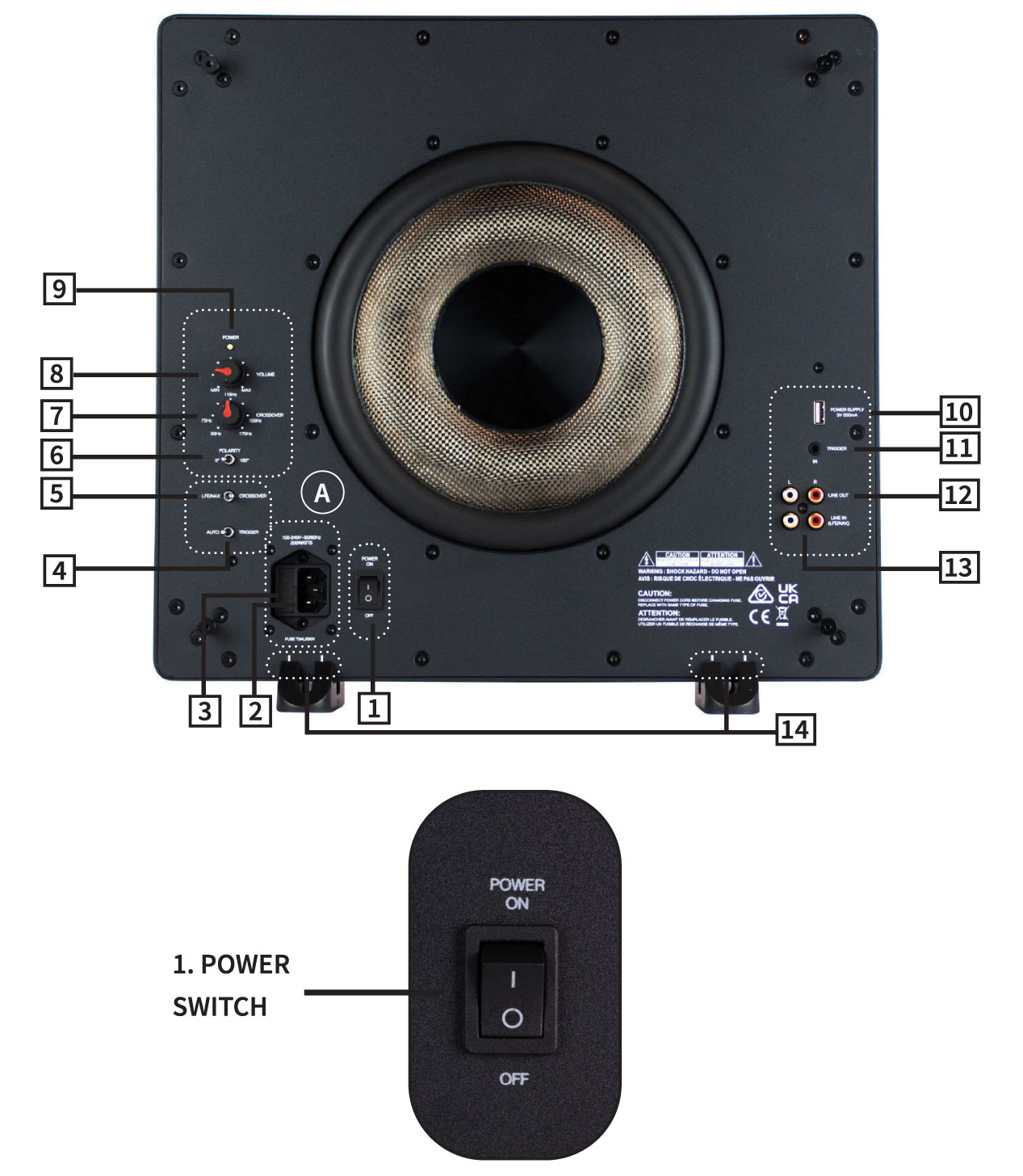
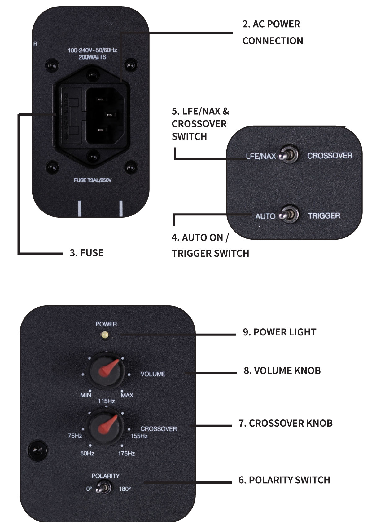
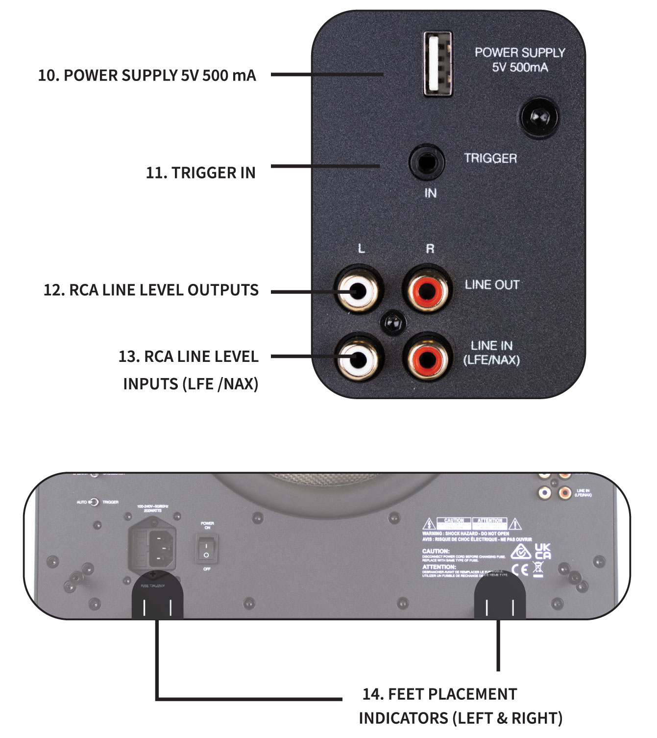
Subwoofer Parts and Controls Guide
1. Power Switch – Switch between On/Off.
2. AC Power Connection – This connection is a standard IEC power jack. Use the supplied 90 Degree, AC Power Cord, to connect the subwoofer to an available and easily accessible AC outlet.
3. Fuse – Additional fuse included for servicing.
4. Auto On / Trigger Switch – This switch functions only when the Power Switch is set to “On.” When the Power Switch is set to “On,” and when this switch is set to “Auto,” the subwoofer’s power will come on automatically, when it senses an incoming audio signal. If there is no signal for 15-18 minutes, the subwoofer will then automatically go into Stand-by.
When the switch is set to “Trigger,” it will power on when it gets a 12V signal from the 12V Trigger Input.
5. LFE/NAX & Crossover Switch – When the switch is set to LFE/NAX, the Crossover Knob will not work, and it will play according to the crossover that was set up in the AV Receiver. When Crossover is selected, you can adjust the crossover point using the Crossover Knob.
6. Polarity Switch – Switches the Polarity between 0 – 180 Degrees.
7. Crossover Knob – Use this knob to set the highest bass frequency the subwoofer will play, from 50 to 175 Hz. If the subwoofer is installed in a stereo system, set this knob as close as possible to the lowest rated bass extension of the main left and right speakers.
Note: For the Crossover Knob to work and adjust the the Crossover Frequency, the Crossover Switch must also be engaged.
8. Volume Knob – This knob adjusts the subwoofer’s volume. Turn it clockwise for full volume. Note that the subwoofer level control in an AV Receiver will also affect how loud the subwoofer plays. With most AV Receivers, setting this knob at about halfway up (the 12 o’clock position) will provide a volume level that allows the subwoofer’s level to be matched with that of the main speakers.
9. Power Light – Red: STANDBY | No Light: OFF | White: ON/OPERATING.
A white light indicates the subwoofer is powered on.
10. Power Supply 5V 500 mA – Use the 90 Degree USB Dongle to power the WSK200 Wireless Transmission Kit by the Subwoofer, through a USB cable to the 5V/ 500 mA power supply.
11. RCA Line Level Inputs
LINE IN (LFE/ NAX): Connects the left female RCA input to an LFE output connection on an AV Receiver or Pre-Amp Processor. Use the included 90 Degree RCA cable. Note, that using L/R RCA inputs will require the LFE/ NAX Switch on the subwoofer to be engaged.
LINE IN (L/R Inputs): Connects the left and right female RCA input to the left and right from output connections on an AV Receiver or Pre-Amp Processor. Use the included 90 Degree RCA cable. Note, that using L/R RCA inputs will require the Crossover Switch on the subwoofer to be engaged..
12. RCA Line Level Outputs
OUT: Connects additional amplifiers.
13. Trigger IN – Turns on the amp when a 12V signal is received from another 12V trigger device.
14. Feet Placement Indicators (Left & Right) – If you are placing the Subwoofer in a Standing Position, place the 2 included Standing Feet directly below the left and right double white line indicators, for a balanced and stable placement.
! CAUTION: All connections and switching must be done with the amplifier turned off. Connect the power cord last to ensure that the amplifier is off during all the connections and setup.
Subwoofer Connection Details
LINE LEVEL INPUTS
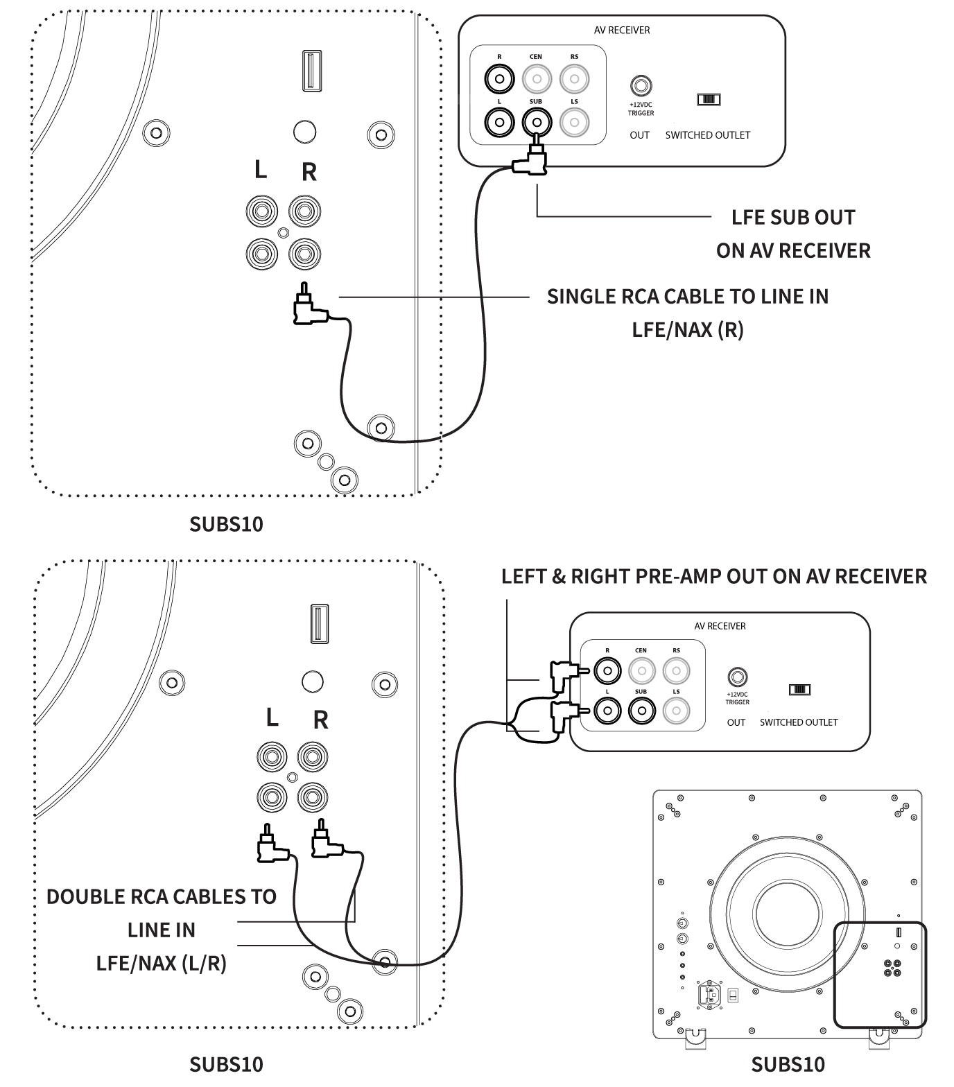
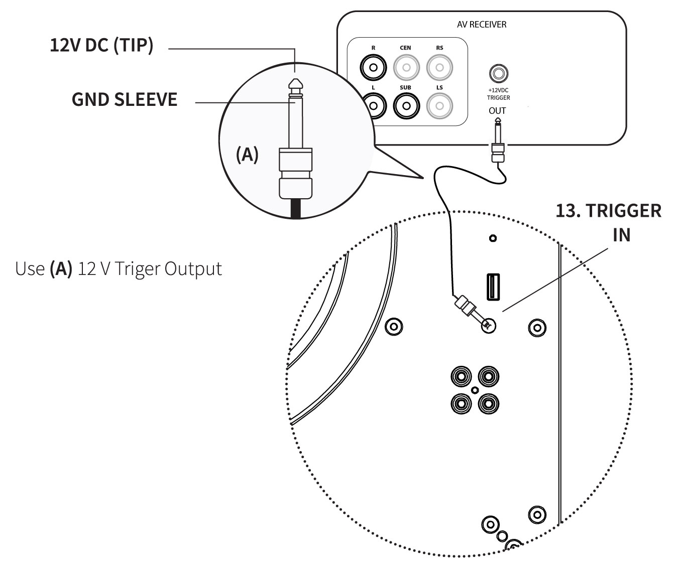
12V DC TRIGGER
Connect the 12V trigger output of another device to the 12V trigger input of the amplifier using a high-quality mono cable.
Connect the appropriate conductor to each screw terminal, observing correct polarity.
Wireless Transmission
Please use Origin Acoustics’ WSK200 (Seperate Purchase) to connect the SUBS10 Subwoofer to a line-level source. Either LFE or Line Level can be selected, but only one is sufficient.
Wireless Subwoofer Kit: WSK200
| RECEIVER | TRANSMITTER |
| Operating Voltage: DC 5V / 0.5A | Operating Voltage: DC 5V / 0.5A |
| RF Frequency Band: 5135 MHz – 5820 MHz | RF Frequency Band: 5135 MHz – 5820 MHz |
| Modulation: GFSK | Modulation: GFSK |
| Working Distant: 40 Meters / line of sight | Working Distant: 40 Meters / line of sight |
| Transmitter Power: less than 10 dBm | Transmitter Power: less than 10 dBm |
| Receiver Sensitivity: N/A | Receiver Sensitivity: -81 dBm |
| Frequency Response: 20-20K Hz | Frequency Response: 20-20K Hz |
| Delay Time: less than 16mS | Delay Time: less than 16mS |
| THD+N(dB): -60 Db @1 KHz | THD+N(dB): -60 Db @1 KHz |
| SNR(dB): +85 dB @1 KHz | SNR(dB): +85 dB @1 KHz |
| Dimensions: 2 ⅜” dia x ¾” thick (60mm x 18mm) | Dimensions: 2 ⅜” dia x ¾” thick (60mm x 18mm) |
Wireless Subwoofer Kit Components
1 x Wireless Audio Adaptor Kit Transmitter
1 x Wireless Audio Adaptor Kit Receiver
2 x 3.5 mm to dual RCA Interconnect cable (1m)
2 x USB A to Micro B Power Cables (1.5m)
2 x 5 VDC Power Supplies with USB A Connectors
What You Will Need
• Powered Subwoofer
• AV Receiver, Surround Processor, or 2-Channel Pre-Amp with a Subwoofer Pre-Out, or L/R Line Level Pre-Out
General Placement and Setup Tips
• Place the subwoofer, powered speakers or amplifier at its intended location.
• Try to maintain line-of-sight (no walls or solid barriers) between the transmitter and receiver for best results.
• Receiver should be within 65 feet of transmitter for best results.
• Avoid placing the transmitter next to devices that could create signal interference, such as 5.8 GHZ wireless phones, baby monitors and Wi-Fi routers.
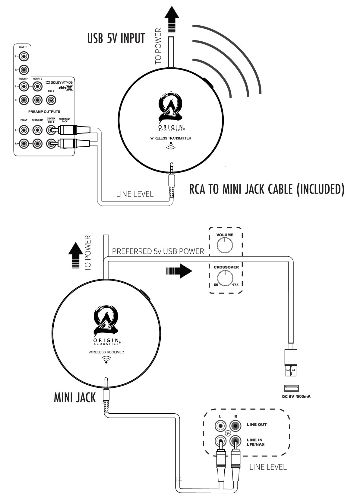
Connecting the Wireless Transmitter to an AV Processor
1. Connect the 3.5 mm to dual RCA adapter cable to the subwoofer pre-out or LFE channel of the AV processor and to the input on the wireless transmitter. Use only one RCA cable channel (e.g.Red). The other RCA connector is unused in this case.
2. Connect the USB A to Micro B cable to the wireless transmitter and the 5V DC power supply.
3. Connect the 5V DC power supply to a 120V AC outlet.
Connecting the Wireless Transmitter to a 2-Channel Stereo Pre-Amp
1. Connect the 3.5 mm to dual RCA adapter cable to the L/R line level pre-outs of the 2-channel stereo pre-amp and to the input on the wireless transmitter.
2. Connect the USB A to Micro B cable to the wireless transmitter and the 5V DC power supply.
3. Connect the 5V DC power supply to a 120V AC outlet.
Connecting the Wireless Receiver to your Subwoofer
1. For AV processor applications, connect the 3.5 mm to dual RCA adapter cable to the LFE input and the input on the wireless receiver. Use only one RCA cable channel (e.g. Red). The other RCA connector is unused in this case.
2. For 2-channel stereo pre-amp applications connect the 3.5 mm to dual RCA adapter cable to both the L and R subwoofer inputs and to the input on the wireless receiver.
3. Connect the USB A to Micro B cable to the wireless receiver and the 5V DC Power Supply. (Or alternatively, connect the 5V DC power supply to a 120V AC outlet.)
Pairing the Transmitter and Receiver
1. The transmitter and receiver are synched at the time of manufacture and will pair automatically when connected and powered on.
2. Successful pairing will be indicated by a steady blue light on the transmitter and receiver.
3. A flashing light indicates the units are not paired. To re-pair the units, perform the following actions:
4. Press and hold the small button on one unit (it doesn’t matter which one you select) until the blue light starts blinking.
5. Immediately walk over to the other unit and press/hold the small button until the blue light starts blinking.
6. Both will blink a few times then turn solid blue when they are successfully paired.
Subwoofer Mounting Options
In Preparation
Unbox the Subwoofer and set box and packing material aside. Turn off the entire audio system before making any connections. If it will be mounted, take care to ensure the Subwoofer is mounted securely into its mount.
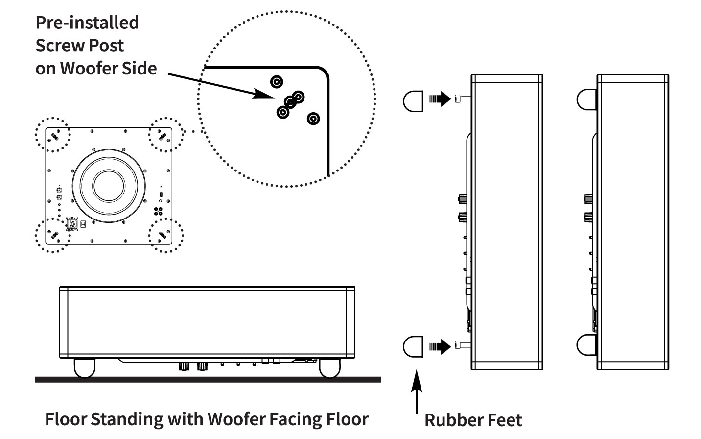
Floor Standing: with Woofer Facing Floor
1. The horizontal floor standing option, where the woofer is facing the floor, requires the included 4 x Rubber Feet, and uses the 4 x Pre-installed Screw Posts on the Woofer Side of the unit.
2. Carefully push down each Rubber Foot, over the corresponding Screw Post, until the Screw Post head meets the Rubber Foot interior, fitting into place.
3. Lay the Subwoofer Unit horizontally across the floor, resting over the attached 4 x Rubber Feet. The Grille cannot be used with this option.
Floor Standing: with Woofer Facing Room
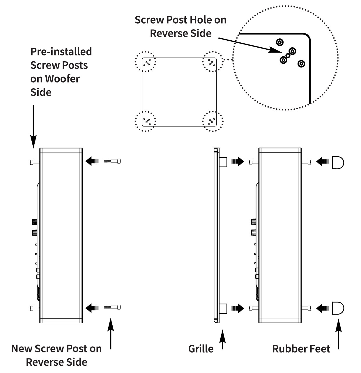
1. The horizontal floor standing option, where the woofer is facing the room, upwards, requires the included 4 x Screw Posts & 4 x Rubber Feet.
2. Screw each Screw Post into the dedicated corner screw holes on the reverse side of the Woofer, and tighten using an allen key.
3. Carefully push down each Rubber Foot over the corresponding Screw Post, until the Screw Post head meets the Rubber Foot interior, fitting into place.
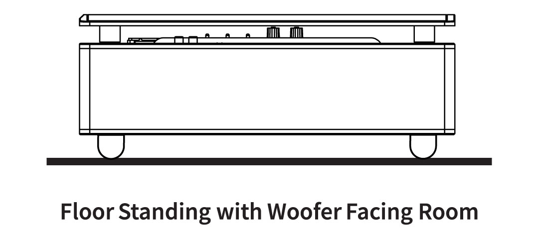
4. Lay the Subwoofer Unit horizontally across the floor, resting on the attached 4 Rubber Feet, so the woofer is facing upwards.
5. Now, the Grille can be placed over the 4 x Pre-installed Screw Posts on the Woofer Side of the unit, fitting securely into place.
Floor Standing: with Woofer Vertically Upright
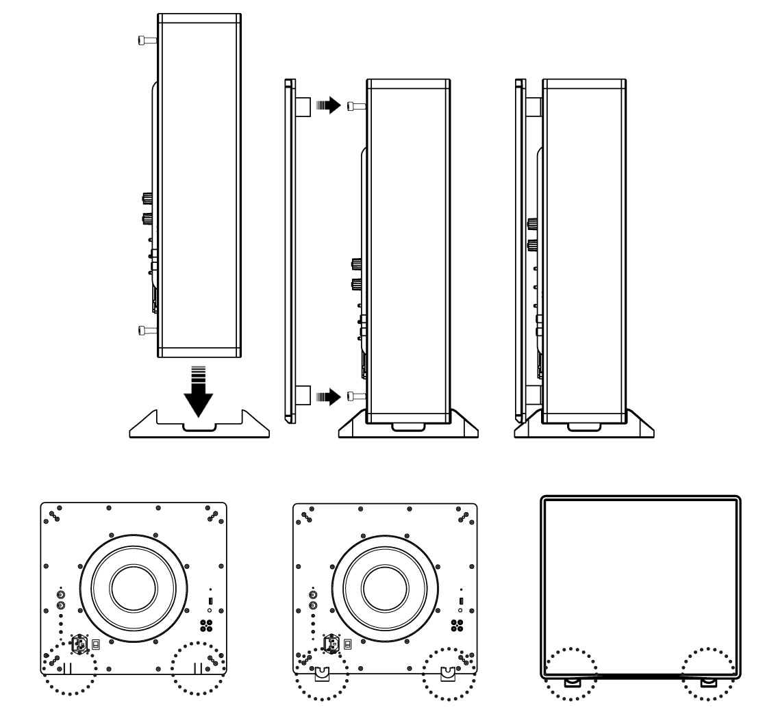
1. The vertical floor standing option, where the woofer is facing sideways, or vertically upright, requires the included 2 x Standing Feet.
2. Locate the left and right double white line indicators on the unit. Place the 2 included Standing Feet directly below, for a balanced and stable placement.
3. Now, the Grille can be placed over the 4 x Pre-installed Screw Posts on the Woofer Side of the unit, fitting securely into place.
Wall Mounted: with Woofer Facing Wall
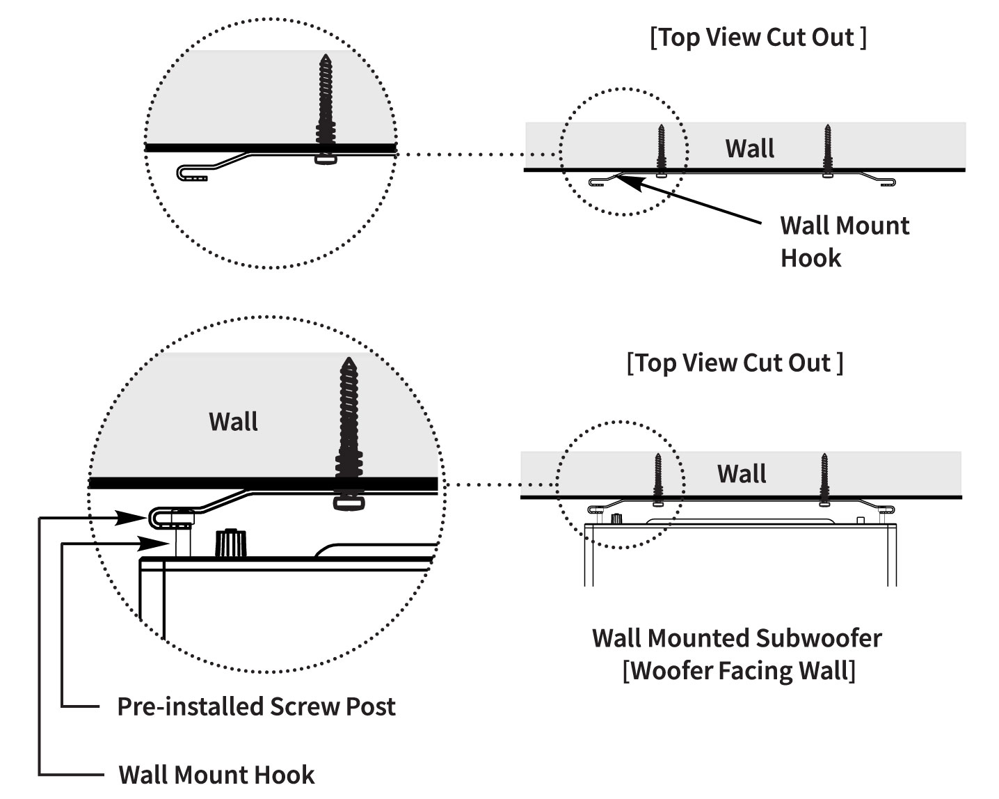
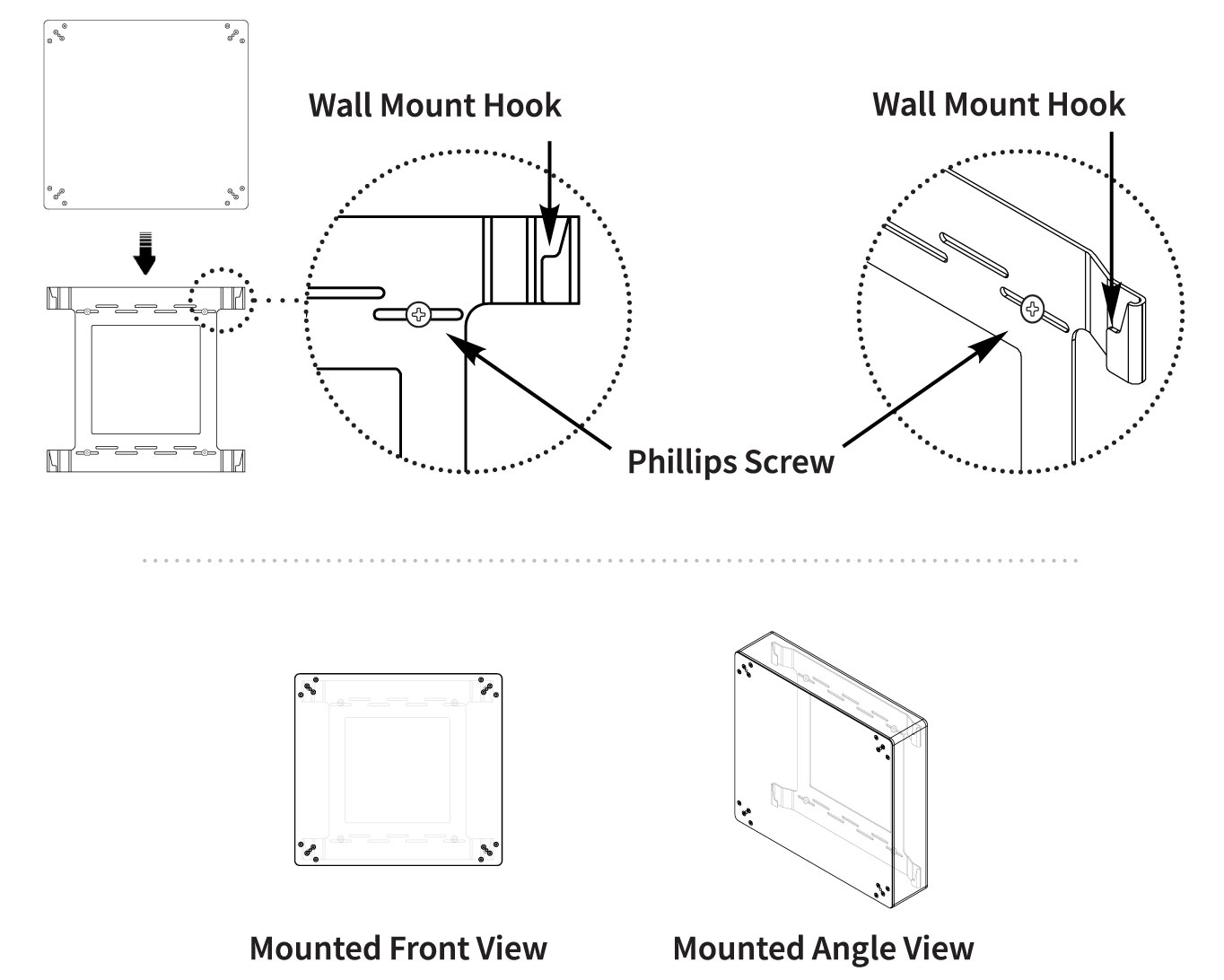
1. The wall mounted option, where the woofer is facing the wall, requires the included Wall Mount, 4 x Phillips Screws, 4 x Drywall Anchors, and uses the 4 x Pre-installed Screw Posts on the Woofer Side of the unit.
2. Place the Grille over the 4 x Pre-installed Screw Posts on the Woofer Side of the unit, fitting securely into place.
3. Now, attach the Wall Mount to the desired location on the Wall. Use the 4 x Phillips Screws between the appropriate horizontal screw holes, if placing it over wooden posts, or with the 4 x Drywall Anchors if placing it over drywall.
4. Carefully slide the Subwoofer Unit into the Wall Mount, with the woofer facing the wall. Ensure each Screw Post slides down and rests inside each corresponding Hook on the Wall Mount.
Wall Mounted: with Woofer Facing Room
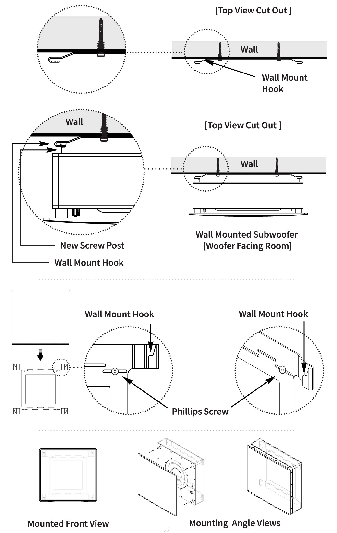
1. The wall mounted option, where the woofer is facing the room, requires the included Wall Mount, 4 x Screw Posts & 4 x Rubber Feet.
2. Screw each Screw Post into the dedicated corner screw holes on the opposite side of the Woofer, and tighten using an allen key.
3. Carefully push down each Rubber Foot, over each corresponding Screw Post, until the Screw Post head meets the Rubber Foot interior, fitting into place.
4. Lay the Subwoofer Unit horizontally across the floor, resting on the attached 4 Rubber Feet, so the woofer is facing upwards.
5. Now, the Grille can be placed over the woofer and slotted into place, fitting the 4 x sockets on the back over the 4 x Screw Posts.
Troubleshooting
If you have a problem, try isolating it first. For example, if you’re playing a DVD and there is no sound, try replacing the DVD with an MP3 player to see if you get sound. If it does work, then the problem is with the television, DVD player, or the cables connecting them. If it doesn’t work, the problem will be with the amplifier, speakers, or those cables.
Common Solutions
| PROBLEM | POSSIBLE CAUSES |
|---|---|
| NO SOUND | The volume may be turned down or muted. Check the volume settings volume may be turned down or muted. Check the volume settings on both the amplifier and the DVD player/ television/ computer/ etc. |
| NO SOUND | Make sure the proper source is selected on the amplifier or receiver. |
| NO SOUND | Check the cord connecting the amplifier with the source. The cord may be damaged or plugged into the wrong input or output. |
| NO SOUND | Check the wires connecting the amplifier with the speakers. Make sure they’re connected properly and not damaged in any way. |
| POOR SOUND QUALITY | If you hear something like static, or the sound is cutting in and out, check the audio cables. If the problem increases when a cable is being moved, then the cable is most likely faulty or not connected properly. |
| POOR SOUND QUALITY | Today’s audio systems may have several places to adjust the volume, for example your MP3 player may have a volume control, and your amplifier may also have one. Check to be certain that the volume isn’t turned up past 80% on any device. |
| POOR SOUND QUALITY | Try changing sources to be certain that the selection you’ve chosen is a good quality recording. |
Technical Assistance
If you have any questions or concerns about installing or using this product, you can reach us through one of the following methods:
Phone: (844) 674-4461
Hours of operation: 8:00am – 5:00pm (Pacific Time), Mon – Fri
Email: sales@originacoustics.com
If you are having technical trouble, please include the model number and briefly explain what steps you took to resolve the problem in your email, or be prepared to answer these questions over the phone. If you are considering returning the product, it’s required that you contact Origin Acoustics prior to any return attempts. This way we can determine if the issue can be resolved without returning the product, or if needed we can provide instructions and support for the return process.
Limited 5-Year Warranty
Origin Acoustics warrants to the original retail purchaser only that for a period of five (5) years from the original date of purchase. This Origin Acoustics product will be free from defects in materials and workmanship, provided the speaker was purchased from an Origin Acoustics authorized dealer.
If the product is determined to be defective, it will be repaired or replaced at Origin Acoustics’ discretion. If the product must be replaced yet it is no longer manufactured, it will be replaced with a model of equal to or greater value that is the most similar to the original. If this is the case, installing the replacement model may require mounting modifications; Origin Acoustics will not be responsible for any such related costs.
Requirements & Coverage
This warranty may not be valid if the product was purchased through an unauthorized dealer. This warranty only applies to the individual that made the original purchase, and it cannot be applied to other purchases. The purchaser must be prepared to provide proof of purchase (receipt). This warranty will not be valid if the identifying number or serial number has been removed, defaced, or altered.
Not Covered by Warranty
- Accidental damage
- Damage caused by abuse or misuse
- Damage caused by attempted repairs/modifications by anyone other than Origin Acoustics or an authorized dealer
- Damage caused by improper installation
- Normal wear, maintenance, and environmental issues
- Damage caused by voltage inputs in excess of the rated maximum of the unit
- Damage inflicted during the return shipment
Return Process
Before making any return attempts, it is required that you first contact Origin Acoustics. Return product to Origin Acoustics or your dealer, either in person or by mail. It’s preferable if the product is returned in the original packaging. If this isn’t possible, the customer is responsible for insuring the shipment for the full value of the product.
This warranty is in lieu of all other expressed or implied warranties. Some states do not allow limitations on implied warranties, so this may not apply depending on the customer’s location. (For more information, see Magnuson-Moss Warranty Act.)
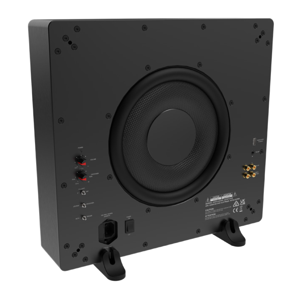
| SUBS10 | |
| Woofer: | 10” Woven Fiber Glass |
| Frequency Response: | 35Hz – 175Hz [+/- 3dB] |
| Power RMS: | 200 Watts |
| Power Peak: | 400 Watts |
| Enclosure: | Aluminum Cabinet |
| Width: | 15 3/4” W [400mm] |
| Height: | Without Feet: 14 ⁹⁄₁₆” [370mm] With Feet: 15 ³⁄₁₆” [386mm] |
| Depth: | Without Grille: 3 ⁹⁄₁₆” [90mm] With Grille: 4 ¹¹⁄₁₆” [119mm] |
| AMP Functions: | • Crossover • Phase • Volume • RCA line in • LFE in • USB input for powering wireless receiver • Auto On/ Off/ Trigger |